


❏
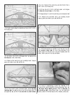
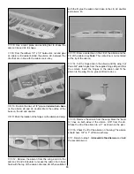
11. Glue the die-cut 3/32" balsa aft stabilizer doublers
to the inside of both fuse sides. Align the top of the doubler
with the top of the fuse side and the front edge of the notch
in the doubler with the aft edge of the top longeron. The aft
edge of the doubler will be approximately 3/8" forward of the
aft edge of the fuse side.
❏
12. Glue the die-cut 1/8" plywood landing gear supports
to the lower fuse doublers. Align the landing gear support
with the top and front of the notch for the landing gear rail.
❏
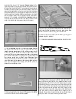
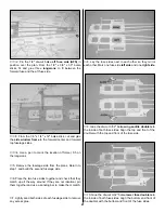
13. Use 6-minute epoxy to glue the front of die-cut plywood
firewall former F-1B to the back of former F-1A. Note: The
side with the embossed lettering on it is the front of the formers.
❏
14. Use 6-minute epoxy to glue the two die-cut 1/8"
plywood firewall spacers to the back of F-1B on the left
side. The spacers will set the right thrust in the firewall when
the firewall is installed in the fuselage.
❏
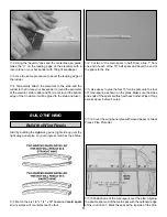
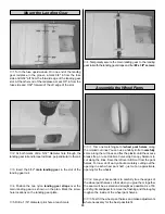
15. After the epoxy has cured, drill 5/32" holes at the four
engine mount punch marks. NOTE: If you will be using an
engine mount other than the Great Planes engine mount,
draw centerlines connecting the outer punch marks. Use the
centerlines to align your engine mount on the firewall. Drill
5/32" holes at the appropriate locations.
❏
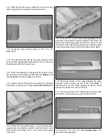
16. Press four 6-32 blind nuts into the holes from the back
of the firewall. Tap the blind nuts with a hammer to fully seat
them. Apply a few drops of thin CA around each blind nut to
secure them in position. Avoid getting CA on the threads of
the blind nuts.
IF USING GREAT PLANES ENGINE MOUNT,
DRILL 5/32" HOLES FOR BLIND NUTS
IF NOT INSTALLING THE GREAT PLANES ENGINE MOUNT,
CONNECT THE OUTER PUNCH MARKS TO CENTER THE ENGINE MOUNT
22


