GREAT PLANES Ryan STA-M Скачать руководство пользователя страница 18

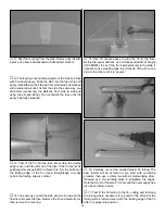
9. Hold the fuselage vertically with the nose pointing

upward. Guide the end of one of the cables with the clevis
attached down through the fuse out one of the holes for the
rudder. Connect the clevis to the torque rod horn on the rudder,
then temporarily fit the rudder to the fin with a the hinges.

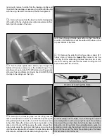
10. Use masking tape to securely hold the rudder

centered. Determine the correct length of the cable so it may
be connected to the rudder servo arm with another brass
coupler and metal clevis. The tension on the cable should be
about the same as a slightly loose guitar string–neither slack
nor taut. Connect the cable to the coupler the same as
before using a swage. Connect the clevis to the rudder servo
arm. On our model, the clevis was connected to the second-
from-the-innermost hole of a Futaba four-arm servo arm.

11. Connect the other rudder cable to the rudder and the

other side of the rudder servo arm the same way. Adjust the
clevises on the threaded couplers so the tension on the
cables is as desired and the rudder is centered when the
servo arm is centered.

12. Now that the rudder hookup is completed, remove the

servo arm from the rudder servo while leaving the pull/pull
clevises connected to it. Pull the rudder from the fin and
disconnect the clevises from the torque rod horns, but leave
the cables inside the fuselage.

13. Cut holes in both halves of the molded plastic rudder

fairing to accommodate the torque rod horns on the rudder.
This is best done with a rotary tool and a cutting bit. Also cut
a slot in both fairings for the bottom rudder hinge.

14. The same as was done for the fin and stab, place the

fairings on the rudder and use a felt-tip pen to mark the top
of the fairing onto the rudder. Cut the covering from the
rudder 1/16" [1.6mm] below the line, but leave part of the
covering around the threaded rod.

15. Use tape or small clamps to hold both halves of the

rudder fairing to the rudder. Be certain the fairing fits well.
Test fit the rudder to the fin with the fairing. Use thin and
medium CA to carefully glue the fairing to the rudder. Note:
Use great care with the CA and use it sparingly so it does
not flow out of the fairing onto the outside of the rudder!

16. Reconnect the clevises on the aft end of the rudder

cables to the torque rod horns on the rudder. Tighten the
nuts on the threaded couplers against the clevises. Join the
rudder to the fin with the hinges. Be certain the hinges
remain centered. If necessary, use pins to keep the hinges
centered, then securely glue in the hinges with thin CA.

17. Attach the servo arm with the cables to the rudder

servo. If necessary, adjust the length and tension of the
rudder cables to get the rudder centered when the servo
arm is centered.

18

Содержание Ryan STA-M

Страница 1: ...sing the user assembled product the user accepts all resulting liability If the buyer is not prepared to accept the liability associated with the use of this product the buyer is advised to return thi...

Страница 2: ...fact a couple of minor improvements make this plane our best ARF yet Although not intended to be an all out scale model the Ryan s classic design and two cockpit layout make it tempting for enthusiast...

Страница 3: ...eck clevises or other connectors often and replace them if they show any signs of wear or fatigue 7 If you are not already an experienced R C pilot you should fly the model only with the help of a com...

Страница 4: ...d on the Ryan an adapter kit for mounting the spinner is not included with this kit and must be purchased separately For the O S 61 SF SX and other two stroke engines with a 5 16 24 crankshaft thread...

Страница 5: ...mm long with forty threads per inch When you see the term test fit in the instructions it means that you should first position the part on the assembly without using any glue then slightly modify or c...

Страница 6: ...w lock connector body 2 4 40 x 1 8 3mm screws for screw lock 2 nylon retainers for screw lock 1 nylon ball link tail steering 1 0 80 threaded ball tail steering 1 0 80 nut for threaded ball 2 1 4 20 b...

Страница 7: ...R L ailerons hinge strip 3 pc ply forward wing joiner ply aft wing joiner 2 wing dowels wing bolt plate GPMA2281 Fuselage Kit Fuselage forward and aft servo trays 4 hardwood cowl mounting blocks 2 coc...

Страница 8: ...the slots For the best result use a high speed tool such as a Dremel Insert a 11 knife blade into the slots working it back and forth a few times to clean the slots out 3 Cut four 3 4 x 1 19 x 25mm h...

Страница 9: ...is mounted in a mirror image with the servo arm pointing toward the middle of the wing and the output shaft toward the trailing edge 5 Thread a nylon clevis twenty full turns onto a 6 150mm threaded...

Страница 10: ...s together until the epoxy has hardened Excess epoxy that gets on the covering can be easily removed before it hardens with a tissue dampened with denatured alcohol or other suitable solvent 6 Round o...

Страница 11: ...he flying field 6 Cut the covering from the grooves in the landing gear rails in the bottom of the right wing panel Trim the rail and the wing sheeting where indicated by the arrow to accommodate the...

Страница 12: ...fuse it helps to have a building stand We use a Robart Super Stand II ROBP1402 1 The same as was done for the ailerons and the wing prepare the elevator stab rudder and fin for hinging by cutting a s...

Страница 13: ...tab While keeping the stab centered from side to side adjust the stab and slide the tape along the string until the arrow aligns with both ends of the stab Be certain the stab remains centered side to...

Страница 14: ...ertical 14 The same as you did the stab draw a line around the fin where it meets the fuse Remove the fin and carefully cut then remove the covering 15 Use 30 minute epoxy to glue the fin to the fuse...

Страница 15: ...to hold the template to the firewall aligning the lines on the template with the lines on the firewall if necessary extend the lines on the firewall with a straightedge and a pen Mark the center of t...

Страница 16: ...est alignment of the throttle servo with the carburetor arm on the engine As can be seen in the photo at step 6 on page 21 the forward servo tray in this model was mounted with the throttle servo near...

Страница 17: ...t contact the edges when the rudder is moved back and forth 4 Slip a small copper tube also called a swage and a threaded brass coupler with a clevis about 6 150mm onto one end of the braided steel ru...

Страница 18: ...levises from the torque rod horns but leave the cables inside the fuselage 13 Cut holes in both halves of the molded plastic rudder fairing to accommodate the torque rod horns on the rudder This is be...

Страница 19: ...h silver solder GPMR8070 by touching the solder to it The heat of the pushrod should melt the solder not the flame of the torch or soldering iron thus allowing the solder to flow Note Do not use silve...

Страница 20: ...CA work quickly If necessary use a small mallet or a wood block to tap the tubes down into the holes before the CA takes hold 5 Mount the tail gear to the fuse with the straps and four 2 x 1 2 13mm sc...

Страница 21: ...Great Planes Dead Center Hole Locator GPMR8130 shown in the photo or another method to mark the locations of the holes for mounting the engine 3 Remove the engine mount from the firewall Drill 29 or 9...

Страница 22: ...the edges 3 Determine your engine exhaust configuration With the O S MAX 91 Surpass II used on this model an O S in type exhaust header pipe OSMG2624 was used to position the muffler near the bottom...

Страница 23: ...cowl 3 32 to 1 8 2 to 3mm is suitable Holding the cowl in position drill 3 32 2 4mm holes through the cowl and the center of the cowl mount blocks Remove the cowl Enlarge the holes in the cowl with a...

Страница 24: ...del to minimize or eliminate the requirement for additional ballast but the model shown in this manual required no tail weight with the components mounted where shown Be certain the receiver and batte...

Страница 25: ...wing 4 Remove the strut and enlarge the hole in the strut only with a 1 8 3 2mm drill Mount the bottom of the strut to the wing with a 4 x 5 8 16mm screw 5 Mount the top of the strut to the fuselage...

Страница 26: ...the other cockpit the same way 8 Trim the molded plastic turtledeck to fit the fuse then temporarily fit it into position Trim the rear cockpit coaming to accommodate the turtledeck 9 The same way a...

Страница 27: ...eceiver but it s easier to operate with the wing off the fuselage Place the wing on a stand next to the fuselage then connect the Y connector from the ailerons to a servo extension cord and connect th...

Страница 28: ...sing a C G Machine lift the model upside down at the balance point marked on top of both sides of the wing using the tip of your middle finger on both hands This is where the model should balance for...

Страница 29: ...CAP0270 Carefully balance the propeller before flying Balance a few spare propellers as well An unbalanced prop is the single most significant cause of vibration that can damage your model Not only wi...

Страница 30: ...e in a closed room or garage Get help from an experienced pilot when learning to operate engines Use safety glasses when starting or running engines Do not run the engine in an area of loose gravel or...

Страница 31: ...the throttle As the model gains speed decrease up elevator allowing the tail to come off the ground Be ready to apply right rudder to counteract engine torque Gain as much speed as the runway and fly...

Страница 32: ...the tail on the ground One final note about flying the Ryan or any model Have a goal or flight plan in mind for every flight This can be learning a new maneuver s improving a maneuver s you already kn...

Отзывы: