background image

6

Enlarge as
necessary

❏ 

5. The front bearing on some motors protrudes slightly 

from the front of the motor. If this is the case for your motor, 
use a Dremel with a tile cutter bit and/or a small drum sander 
to enlarge the hole as necessary. Proceed 

slowly

 and 

with 

care

 to keep the hole centered and so as not to over enlarge 

the hole—this may require test-fi tting the motor as you 
proceed. 

CAUTION:

 Wear protective gloves, a long-sleeve 

shirt and breathing and eye protection 

whenever

 working 

with carbon fi ber.

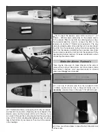
❏ 

6. Test-mount the motor with your motor mounting 

screws—if using the recommended Ammo motor you may 
use the M3 x 5 screws included with the motor, but some 
prefer button-head Allen screws instead (such as the screws 
shown in the photo—HPIC3250).

PROPELLER MOUNTING

The collet shaft included with your Rifl e spinner is designed 
to work with the small O.D. propeller spacer ring that comes 
with all APC 

speed 400

 propellers. 

❏ 

A. To prep the prop, press the spacer all the way into 

the propeller hub. Then use a #11 blade to carefully trim 
any fl ashing from around the inside of the spacer. 

❏ 

B. Firmly press the propeller onto the collet shaft.

❏ 

C. An 8mm wrench is a must for your tool box. A Traxxas 

8mm fl at wrench is pictured here (TRAR5478).

Содержание Rifle 1M

Страница 1: ...of using the user assembled product the user accepts all resulting liability If the buyer is not prepared to accept the liability associated with the use of this product the buyer is advised to return this kit immediately in new and unused condition to the place of purchase To make a warranty claim send the defective part or item to Hobby Services at the address below Hobby Services 3002 N Apollo ...

Страница 2: ...ut rather a sophisticated working model that functions very much like a full size airplane Because of its performance capabilities the 1M if not assembled and operated correctly could possibly cause injury to yourself or spectators and damage to property 2 You must assemble the model according to the instructions Do not alter or modify the model as doing so may result in an unsafe or unflyable mod...

Страница 3: ...eatures in flight data logging To take advantage of Data Logging and view important information such as current Watts RPM etc the Castle Link USB Programming Kit is also required CSEM9999 See page 18 for discussion and more data about these two setups including Watts current flight time propellers options etc Radio Control System To take full advantage of the dual aileron servos a 5 channel program...

Страница 4: ...any To locate a hobby dealer visit the Great Planes web site at www greatplanes com Choose Where to Buy at the bottom of the menu on the left side of the page Follow the instructions provided on the page to locate a U S Canadian or International dealer Parts may also be ordered directly from Hobby Services by calling 217 398 0007 or via facsimile at 217 398 7721 but full retail prices and shipping...

Страница 5: ...ifferent motor in the future don t be too concerned about the possibility of new motor mounting screw holes that may overlap or interfere with the old holes Most of the mounting patterns are standard We ve mounted both Ammo motors and other motors to a couple of different Rifles and although four more holes were required this didn t present any problems 3 Using the plywood template as a guide dril...

Страница 6: ...ount the motor with your motor mounting screws if using the recommended Ammo motor you may use the M3 x 5 screws included with the motor but some prefer button head Allen screws instead such as the screws shown in the photo HPIC3250 PROPELLER MOUNTING The collet shaft included with your Rifle spinner is designed to work with the small O D propeller spacer ring that comes with all APC speed 400 pro...

Страница 7: ...toff wheel works best Wear safety glasses and protect the motor from metal dust while cutting 9 Use a metal file or sandpaper to deburr the end of the shaft Remount the motor and test fit the spinner to see if the gap is right Make adjustments if necessary Prepare the Motor and ESC 6 1 2 7 165mm 175mm 1 As shown in the illustration at step 1 on page 5 the ESC fits best inside the fuselage resting ...

Страница 8: ... and a battery so you can run the motor with the transmitter Make sure the motor is turning in the correct direction If not disconnect the ESC from the motor and re connect it with the wires in a different order so the motor will be turning the correct direction 7 IMPORTANT Slip three more pieces of 3 16 5mm shrink tubing over each bullet connection and shrink with a heat gun to make sure the conn...

Страница 9: ...A 5 Temporarily connect your elevator servo and ESC to the receiver with a battery and turn on the transmitter so you can power the servo Again make certain there are no mixes setup in your transmitter and that all the trims and sub trims are zeroed 6mm 8mm 90 6 Use a servo arm that has holes 6mm 8mm out Position the arm on the servo so it will be 90 or as close as 90 as possible If necessary dial...

Страница 10: ... the end again Add a thin film of oil to the pushrod and then reinstall in the fuselage 11 With the elevator servo laying flat on the bottom of the fuselage make a sharp 90 bend to the left 1 4 6mm from the end 12 Temporarily connect the elevator horn to the pushrod and mount the horizontal stabilizer to the top of the fuselage with the two included M3 x 10 flat head Phillips screws Move the eleva...

Страница 11: ... Goo PAAR3200 is recommended for gluing in the servos Goo adheres extremely well yet is just flexible enough so that if ever necessary the servos can be extracted Any residual Goo can be peeled off the servos and the plane making it easier to remount new servos again 16 Clean the servo mounting surface and the bottom of the fuselage with a cloth dampened with denatured alcohol Turn on your transmi...

Страница 12: ... 75mm servo extension This way when downloading data all you will have to do is disconnect the ESC from the extension rather than disconnecting the ESC from the receiver simplifying the procedure Also label the two aileron extensions coming from the receiver with the appropriate channel numbers for easier identification when connecting the ailerons later Make the Aileron Pushrods There may be othe...

Страница 13: ...the fuselage from the receiver Connect a battery and turn on the transmitter so you can operate the servos Program a mix so the servos respond opposite each other in the correct direction to aileron control stick inputs 5 10 5 10 Right aileron servo Left aileron servo 2 Same as was done for the elevator servo connect servo arms that will be angled slightly forward at about a 5 to 10 angle Cut off ...

Страница 14: ...rod and placed over the hatch Make sure the horn and servo align and that the arm and pushrod are centered in the opening If necessary adjust the bends in the ends of the pushrod to achieve this alignment 9 Use 30 minute epoxy to securely glue the aileron horn into the aileron 10 Repeat the previous three steps for the right aileron servo 11 The same way you glued down the elevator servo clean the...

Страница 15: ... 2 Mark the leading edge of the bottom of the wing in alignment with the tips of the dowels 1 3 16 30mm Recommended starting balance point 3 Lay 2 50mm strips of vinyl tape or similar on the bottom of the wing aligned with the marks Use a fine point felt tip pen to draw lines across the strips 7 8 1 3 16 and 1 1 2 22mm 30mm and 38mm back from the leading edge 4 Attach a strip of the softer loop si...

Страница 16: ...ion of the battery that allows the Rifle to balance remove the wing and mark the battery location so it will be repeatable out at the flying field 8 Bevel the front of the included plastic battery spatula and slide it under the battery for easier removal Set the Control Throws 1 Remove the propeller and spinner 2 Connect the battery to the ESC and turn on the transmitter If necessary adjust the su...

Страница 17: ... deployment of spoilerons the Rifle will initially balloon upward but after it bleeds off enough speed and nears the landing zone the up elevator mix will partially dampen out your minute elevator corrections helping maintain a more even glide path It is recommended to link your spoilerons to an easily accessible adjustable slider or dial so you can modulate the precise degree of spoilerons depend...

Страница 18: ...n in the table at the bottom of the page the sport setup will draw about 34A at full throttle in flight and the speed setup will draw about 45A at full throttle in flight To convert this to flight time divide the capacity you wish to drain from your battery the size of your fuel tank by the current and convert to minutes You should strive to consume no more than 80 of your battery during a flight ...

Страница 19: ... in severe injury to yourself and others Wear safety glasses whenever running motors Keep your face and body as well as all spectators away from the plane of rotation of the turning propeller Keep loose clothing and objects such as pencils or screwdrivers that may fall out of shirt or jacket pockets away from the prop One final note Do not fly unless your senses and decision making abilities are sh...

Страница 20: ...ll be simply to fly it Remember to throttle back and fly a circuit before reaching for the trims Flying Once your Rifle is airborne the first order of business will be to get it trimmed for straight and level flight You can nudge the trims yourself or have your assistant work the trims for you while you focus on flying the plane One of the initial challenges of flying the Rifle is keeping it withi...

Страница 21: ... more head wind there is the nearer your approach can be and the easier it will be to track the Rifle all the way in 2 Continue increasing up elevator holding holding holding the Rifle off the ground until it just won t stay airborne anymore and finally touches down 1 Gradually increase up elevator floating the Rifle about a foot or so above the ground When the Rifle is a foot or so off the ground...

Страница 22: ... when you begin flying more frequent high speed pylon style turns you ll want to make sure the Rifle is laterally balanced and turns correctly When performing a full throttle pylon turn roll the wing vertically then pull full low rate elevator Notice whether the plane rolls in either direction with the application of only elevator If the high wing rolls out of the turn it will probably also yaw up...

Страница 23: ...th motors in the 120g 140g range 40mm 50mm in length This is pretty much what you ll get with the recommended 3S Ammo speed setup We understand that the tendency for this type of plane is to stuff in as much power as possible and we ve already done that ourselves but in order to get all this power you ll need a bigger motor ESC and battery Then the Rifle becomes heavier making it less practical ei...

Страница 24: ......

Отзывы: