GREAT PLANES QUIK-V6 Скачать руководство пользователя страница 28

28


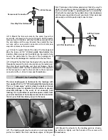
4. Lay the tail covers and MonoKote (or a quarter) on 

the tail. Place the model on your C.G. machine or lift it 
at the balance point to see where it balances. Quik-V6s 
with the 426 Jett setup will tend to not require any ballast 
(depending upon the location of the battery and receiver) 
and sport setups with different engines (that are probably 
slightly heavier than the Jett engine) may require tail ballast.


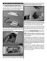
5. If the Quik-V6 doesn’t balance, fi rst try to arrange the 

receiver battery and receiver to get the model to balance, 
then place lead ballast over the nose or on the tail. With 
the sport setup the Quik-V6 may require 1 – 1.5 oz. [30 – 

40g] of ballast on the tail.


5. Arrange the battery and receiver to get the model 

to balance, or add ballast where necessary. Tail ballast 
can be added as shown, but be certain it is 

securely


glued into place—30-minute epoxy is recommended and 
doesn't interfere with the V-tail linkages.

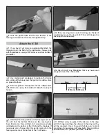
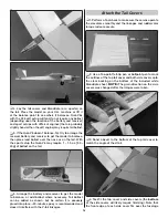
Attach the Tail Covers


1. Perform a fi nal check to make sure the servos operate 

the elevators smoothly and the linkages and ruddervator 
torque rods are secure.


2. Use a fi ne-point felt-tip pen or ballpoint pen to mark 

the outlines of the top tail cover and both side covers onto 
the clear backing on the bottom of the included white 
MonoKote sheet. 

NOTE:

 The grain direction on the side 

covers was changed after the images were taken.


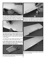
3. Sand a bevel to the bottom of the top tail cover to 

match the angle of the V-tail.


4. Test-fi t the top cover and side covers (the 

bottom 

of the side covers will likely require trimming). Note that 
the front edge of each side cover fi ts 

over

 the fuselage 

Содержание QUIK-V6

Страница 1: ...reat Planes has no control over the final assembly or material used for final assembly no liability shall be assumed nor accepted for any damage resulting from the use by the user of the final user as...

Страница 2: ...ticated workingmodelthatfunctionsverymuchlike afull sizeairplane Becauseofitsperformancecapabilities the Quik V6 if not assembled and operated correctly could possibly cause injury to yourself or spec...

Страница 3: ...ort Quickie Jett Engineering Inc QJ 1 40 engine and muffler Jett back plate mount Jett remote universal needle valve Darrol Cady or Sullivan thin wall fuel tubing SULQ1205 Spare glow plugs Merlin 1125...

Страница 4: ...y your model will fly please expect slight deviations between your model and the published values KIT INSPECTION Before starting to build inspect the parts to make sure they are of acceptable quality...

Страница 5: ...blemish in that area You could always puncture these trouble spots later after you have applied your graphics 2 When ready to apply graphics trim colors may be cut from MonoKote Applying MonoKote over...

Страница 6: ...arden before re cutting the holes with a 10 24 tap later 9 Inspect all visible glue joints looking for areas in the cabin or tail that could use reinforcement Where necessary use a CA applicator to ap...

Страница 7: ...des and the bottom of the wing bolt plates and to the landing gear area as shown You can dip your finger in denatured alcohol to smooth and form the fillets as you go 14 Mix up another batch of epoxy...

Страница 8: ...ial and smooth the edges 2 If necessary enlarge the openings in the servo trays to fit your servos then test fit the servos if the cutouts do require cutting remove material from the aft end of the op...

Страница 9: ...licator glued into position as a bearing for the holes Drill a hole in the switch for the string then mount the switch with threadlocker on the threads and connect the string 7 Mount the servos If usi...

Страница 10: ...otch in the former and the tab on the bottom into the slot in the base Without glue test fit the ruddervators with the hinges torque rods and ball links Make sure the ruddervators move smoothly and th...

Страница 11: ...tely flush with the tube so an aluminum sleeve can be fit over the assembly later 6 Make a Z bend in the wire 5 8 16mm from the end of the tube Cut the excess wire off the end of the Z bend and use a...

Страница 12: ...e pushrod The pushrod was wrapped with masking tape for clarity in the photo Mark the pushrod 1 8 3mm from the ball link and a third mark 1 25mm from the second 12 Cut the pushrod at the second mark m...

Страница 13: ...dhere then install the tubes up through the formers in the fuselage 2 Thread a ball link ball about 3 8 10mm onto each of the pushrod wires 3 Thoroughly clean the pushrod wires with a paper towel squa...

Страница 14: ...view the joint from the bottom Make sure the covering has been trimmed so there will be a full wood to wood glue joint between the bottom of the V tail and the fuselage If necessary use a fine point f...

Страница 15: ...you can get the V tail to align use care sanding a small amount of material can have a drastic effect The stab in the image needs to be rotated clockwise to bring the left tip up and the right tip do...

Страница 16: ...ator to make sure the hinges are secure The wood tail covers will be added after it has been determined whether or not any ballast is required in the tail to achieve the correct C G Mount the Engine I...

Страница 17: ...ngine and fasten the back plate mount with whichever screws are suitable and a drop of threadlocker on the screws 6 Mount the back plate mount to the firewall with four 6 32 x 5 8 16mm SCHS and thread...

Страница 18: ...ttle linkage and lock the pushrod to the screw lock connector with the 4 40 set screw and threadlocker 6 Mount the muffler to the engine Install the Fuel Tank 1 Prepare the fuel tank as shown it would...

Страница 19: ...r or five times around a 3 16 4 8mm tube or rod the coils will get tighter with each wrap until the I D of the last coil is about the same as the tube C Cut off the extra coils so only the last tighte...

Страница 20: ...pick the material out of the counter bore Use your covering iron to make sure the covering is thoroughly sealed to the firewall around the hole 4 Cut the 1 8 3 2mm guide tube for the fuel cut wire to...

Страница 21: ...o 4 x 1 2 13mm screws 9 Remove the screws harden the holes with thin CA allow to harden then mount the needle valve 10 Glue the laser cut 1 8 3 2mm plywood doubler to the bottom of the laser cut 1 8 3...

Страница 22: ...re to the screw lock connector with a 4 40 set screw and threadlocker Mount the Landing Gear The main landing gear is fastened to the fuselage with the supplied 10 24 x 1 2 13mm nylon flat head screws...

Страница 23: ...r Because the tank features a collapsing bladder pressurized between itself and the plastic container only a single pickup line is used inside the tank A Bubble Jett Fuel Tanker syringe type fueler or...

Страница 24: ...he firewall 6 Use additional pieces of foam padding on top of the tank and under the tank as needed As shown the tank was secure and will not shift forward or aft but if a little more security is desi...

Страница 25: ...in CA to both sides of all the hinges 3 After the CA on the hinges has hardened pull hard on each aileron to make sure the hinges are secure In the following steps the aileron hinge gaps will be seale...

Страница 26: ...e the aileron up and down a few times to make sure it moves reasonably smoothly Make any adjustments necessary 12 Seal the top of the aileron and the top and bottom of the other aileron the same way 1...

Страница 27: ...d the ailerons adjusting the length of the pushrods as necessary Install silicone retainers on the clevises and the servo screw in the servo wheel FINAL ASSEMBLY Check the C G This is an initial C G c...

Страница 28: ...et the model to balance or add ballast where necessary Tail ballast can be added as shown but be certain it is securely glued into place 30 minute epoxy is recommended and doesn t interfere with the V...

Страница 29: ...ering from the fuselage sides where the side covers will fit If your technique is to pinch the plane by the tail for launching for a pylon race you may lightly reinforce the side covers by adding smal...

Страница 30: ...imensions in the sketch use a hobby knife and a straightedge to cut the pieces of MonoKote around the outlines you drew 11 Use a covering iron to iron the MonoKote top then the side pieces into place...

Страница 31: ...sconnect the aileron servo wire directly into the receiver every time you install and remove the wing you may also connect a servo extension to the aileron channel in your receiver Final C G Check NOT...

Страница 32: ...ws specified below will be a great starting point and should allow you to be comfortable enough to get the plane low and on the course immediately after the initial trim passes These are the recommend...

Страница 33: ...spectators away from the plane of rotation of the propeller as you start and run the engine Keep these items away from the prop loose clothing shirt sleeves ties scarfs long hair or loose objects such...

Страница 34: ...tuning the C G to adjust the way the plane flies on the course but you need a good starting point and we ll cover adjusting the C G with flight trimming later LATERAL BALANCE Now check the lateral ba...

Страница 35: ...ACK TOWARD PYLON 1 C G Next we ll dial in how the plane flies in the straightaways This depends on what course you ll be flying 2 or 3 pole and the distance In AMA Class 424 and Class 426 we mostly us...

Страница 36: ...V4 showed how good the V3 wing really was We had at least a 2 second advantage on everybody Gary Schmidt and I went to the 95 Nats and were blowing everyone away I ended up getting a zero for a reaso...

Отзывы: