background image

6

BEFORE YOU BEGIN

Before you begin assembling your model, inspect it for 
wrinkled covering and areas where the covering should be 
tacked down to the wood like the openings for the servo 
bays. Use Low heat (about 250° F [121° C]) to tack down the 
edges. Raise the temperature and iron over wrinkles with 
light pressure. Be careful not to contact the edges that you 
tacked down while shrinking. 

Note:

 Save the plastic bag that the fuselage came in. It will 

be used later in the assembly.

WING ASSEMBLY

Aileron Servo Installation

❏ 

1. Prepare a left and a right servo using your radio system 

to center the servos. Remove the servo arm retaining screws 
and the servo arms. Install the standard size servo arms that 
came with your servos. Rotate the arm on the splined servo 
shaft and choose the arm that is 90° to the side of the servo 
case when the servo is centered. Clip off the unused servo 
arms so that your aileron servos appear as shown. Fit any 
servo grommets now (if equipped).

❏ ❏ 

2. Working with the left wing, remove the aileron servo 

bay cover. Center the servo arm in the opening with the arm 
pointing out as shown. With the servo in this position, glue 
two 7mm x 10mm x 14mm hardwood blocks under the servo 
mounting tabs. If you are using the recommended Futaba 
S3115 servos, you may simply use epoxy to glue the blocks 
in the positions marked inside the cover.

❏ ❏ 

3. Drill mounting holes for the servo using a 1/16" 

[1.6mm] drill. Install the two servo screws that came with your 
servo. Remove the screws and the servo and wick a drop of 
thin CA into the screw threads that you just tapped in the 
hardwood blocks. After the CA cures, re-install the screws.

❏ ❏ 

4. Attach a 12" [305mm] servo lead extension to the 

aileron servo. Secure the connection with a piece of 3/8" 
[9.5mm] diameter heat shrink tubing (not supplied) or wrap 
the connection with electrical tape.

Содержание Mister Mulligan EP ARF

Страница 1: ...e act of using the user assembled product the user accepts all resulting liability If the buyer is not prepared to accept the liability associated with the use of this product the buyer is advised to...

Страница 2: ...47302 9252 Tele 800 435 9262 Fax 765 741 0057 www modelaircraft org IMPORTANT Two of the most important things you can do to preserve the radio controlled aircraft hobby are to avoid flying near full...

Страница 3: ...ssed or implied as to the performance or safety of your completed model Remember Take your time and follow the instructions to end up with a well built model that is straight and true ITEMS REQUIRED R...

Страница 4: ...ignated by a number and a length For example 6 x 3 4 19mm Machine screws are designated by a number threads per inch and a length For example 4 40 x 3 4 19mm Socket Head Cap Screws SHCS are designated...

Страница 5: ...ERING REPLACEMENT PARTS Replacement parts for the Mister Mulligan EP are available using the order numbers shown below The fastest most economical service can be provided by your hobby dealer or mail...

Страница 6: ...ervo case when the servo is centered Clip off the unused servo arms so that your aileron servos appear as shown Fit any servo grommets now if equipped 2 Working with the left wing remove the aileron s...

Страница 7: ...small control horn Align the horn over the mark you made and slide it forward until the pushrod holes in the horn are directly over the hinge line Drill two 3 8 9 5mm deep holes using a 1 16 1 6mm dr...

Страница 8: ...t wing as shown so that at least 10mm is protruding Fixed Wing Flap Option 1 On this model you can set up the flaps one of three ways You can purchase two additional servos and use flaps for landings...

Страница 9: ...outline and the holes to center the small oval piece Allow the glue to dry Note The pair that you create will not be mirror images because both flap servo arms must operate in the same direction as t...

Страница 10: ...you prepared the aileron servos using one nylon clevis and a silicone clevis retainer 9 Attach the clevis to the outermost hole in the flap control horn Extend the pushrod forward and mark the point t...

Страница 11: ...ieve mechanically We found that we had to set our end points to 30 40 1 Trim away the covering from the servo arm hole 2 Establish the rotation direction of your flap servos Lay one flap servo on its...

Страница 12: ...s directly over the hinge line Drill two 3 8 9 5mm deep holes using a 1 16 1 6mm drill bit Be careful not to drill completely through the flap Install the control horn using two 2x3 8 9 5mm sheetmetal...

Страница 13: ...see the difference by just looking at them We recommend test fitting both of the landing gear fairings over the main landing gear and checking the fit If they are properly oriented they should fit ag...

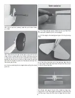
Страница 14: ...assembling the fuselage before putting the wheel pants on Tail Installation 1 Cut the protective piece of balsa wood out of the TE of the horizontal stabilizer slot on the fuselage 2 Fit the wing to...

Страница 15: ...Glue the horizontal and vertical tail to the fuselage using thin CA Wick several generous beads of CA into the tail to fuselage joints Remember to apply glue to both sides and the top and bottom of th...

Страница 16: ...onto the hinges and the tailwheel wire Push the rudder forward up against the fin and remove the T pins Slide the rudder up or down until the top of the rudder is even with the top of the fin Deflect...

Страница 17: ...mpletely through the elevator 5 Install the control horn using the backing plate and two 2 56 x 1 2 12 7mm machine screws Fit the clevis to the outermost hole in the control horn 6 Clip the excess len...

Страница 18: ...a 6 lock nut to secure the screw Now screw a nylon torque rod horn onto the threaded end of the screw so that it is flush with the end Connect the clevis 11 Prepare a servo Install the rudder servo th...

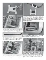
Страница 19: ...tray 6 Cut a 1 1 2 38mm piece of adhesive backed hook and loop material Stick one side to the back of the ESC and the other side to the ESC tray Clean the back side of your ESC with some denatured al...

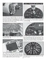
Страница 20: ...stalled rails and drill six 1 16 1 6mm holes into the rails using the holes in the floor panel as guides Install the cabin floor using six 2 x 3 8 sheetmetal screws and six 2 flat washers COWL PROPELL...

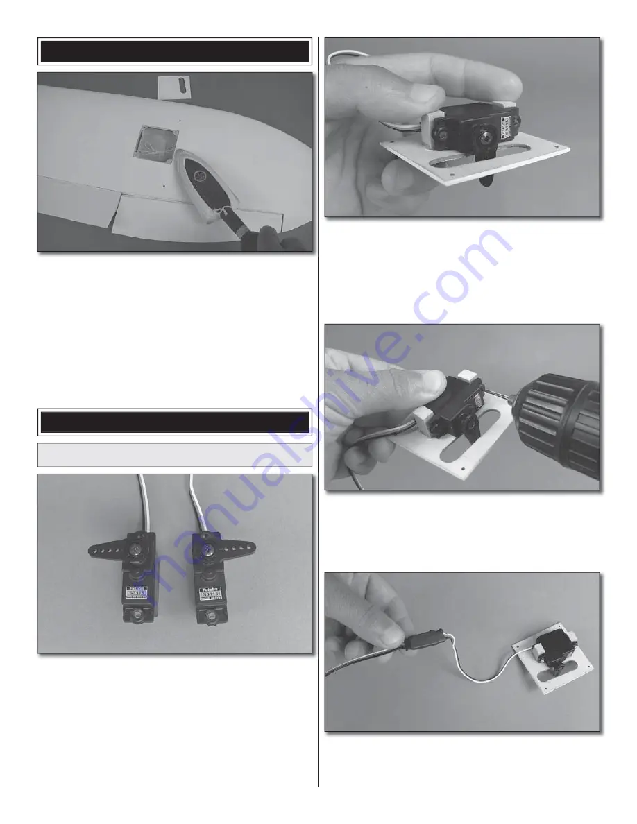
Страница 21: ...d cowl ring to the fuselage with four 4 40 x 1 2 13mm socket head cap screws four 4 lock washers and four 4 flat washers Use a 3 32 ball wrench GPMR8002 to tighten the screws 8 Slide the cowl over the...

Страница 22: ...urely FINAL ASSEMBLY 1 Connect the aileron and flap servo leads to the Y connectors Install the wing using two 1 4 20 nylon wing bolts 2 Identify the two right wing struts Use the picture above to ide...

Страница 23: ...s underneath 2 Position decal on the model where desired Use the photos on the box for reference Holding the decal down use a paper towel to wipe most of the water away 3 Use a piece of soft balsa or...

Страница 24: ...ws using Futaba servos and a Futaba radio system If you are using a different radio system or you cannot achieve the proper control throws using our suggested linkage configuration you may have to ins...

Страница 25: ...eceiver must be shifted forward or weight must be added to the nose to balance If the nose drops the model is nose heavy and the battery pack and or receiver must be shifted aft or weight must be adde...

Страница 26: ...s Get help from an experienced pilot when learning to operate electric motors Use safety glasses when operating motors Do not operate the motor in an area of loose gravel or sand the propeller may thr...

Страница 27: ...place and are tight 11 Reinforce holes for wood screws with thin CA where appropriate servo mounting screws etc 12 Check that all servo connectors are fully plugged into their respective channels on...

Страница 28: ...ps down to see how the plane slows down If this is your first plane equipped with flaps here are a couple of notes on how to land with flaps Only lower the flaps at half throttle or less When the flap...

Страница 29: ...29 Align these dashed lines with the other windows Cut C u t Note Door is only on RH side DOOR TEMPLATE This model belongs to Name Address City State Zip Phone Number AMA Number...

Страница 30: ...30 NOTES...

Страница 31: ...31...

Страница 32: ......

Отзывы: