


11
looking at the aileron at a shallow angle. If you cannot see it, the
plate is approximately 1-5/8" [41mm] wide and will be inline with
the servo arm. Use a T-pin to lightly puncture the covering to be
sure you are over the plywood plate.
❏ ❏
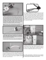
7. Place a heavy duty nylon control horn on the aileron,
positioning it as shown in the sketch inline with the outer hole
of the servo arm. Mark the location for the screw holes. Drill
through the marks you made with a 3/32" [2.4mm] drill bit. (Be
sure you are drilling into the plywood plate mounted in the
bottom of the aileron. Drill through the plate only. Do not drill
all the way through the aileron!). Using a #4 x 5/8" [16mm]
sheet metal screw, install and then remove a screw into each
of the holes. Harden the holes with thin CA. Install the control
horn with four #4 x 5/8" [16mm] sheet metal screws.
❏ ❏
8. Locate a .095" x 6" [2.4mm x 152mm] pushrod wire
threaded on one end. Screw a 4-40 nut, a silicone clevis
retainer and a threaded metal clevis onto the threaded end
of the wire 20 turns. Tighten the nut against the clevis using
threadlocking compound and then install the clevis on the
outer hole of the aileron control horn.
❏ ❏
9. Be sure the aileron servo is centered and the servo
arm is parallel to the hinge line. Install a 4-40 metal solder
clevis onto the outer hole in the servo arm. Center the
servo arm parallel with the aileron hinge line and center the
aileron. Using the solder clevis as a guide, mark where to cut
the pushrod wire. Remove the pushrod and clevis from the
control horn and the solder clevis from the servo arm. Install
another silicone clevis retainer onto the wire and solder the
clevis to the pushrod using the “Expert Tip” that follows.
HOW TO SOLDER THE CLEVIS
TO THE PUSHROD
1.
Where the pushrod will make contact with the solder
clevis, roughen the wire with 220-grit sandpaper.
2.
Use denatured alcohol to remove any oil residue from
the pushrod wire.
Note: Soldering should be done with silver solder, not
an electrical solder.
3.
Apply a couple of drops of fl ux to the wire. Slide the
solder clevis onto the wire. Using a small torch or
soldering iron heat the wire, allowing the heated wire to
heat the solder clevis. Apply a small amount of solder to
the joint. When the wire and the clevis are hot enough
the solder will fl ow into the joint. Avoid using too much
solder, causing solder to fl ow out of the joint and clump.
Use just enough solder to make a good joint. Allow the
wire and clevis to cool.
4.
Put a couple of drops of oil onto a rag and wipe the joint.
This will prevent rust from forming on the joint.
❏ ❏
10. Install the pushrod and clevises to the outer hole in
the servo arm and the outer hole in the control horn. Adjust the
linkage until the aileron and the servo arm are both centered.
Then, tighten the nut against the clevis with threadlocking
compound. Slide the two silicone clevis retainers to the end
of each clevis.
❏
11. Repeat these steps for the right wing panel.
Join the Wing Panels
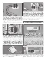
❏
1. Trim the covering from the servo lead cutouts in the
top of the wing panels. Feed the aileron servo leads through
the cutouts. Taping the leads to the top of the wing will keep
them out of the way when joining the wing panels.
❏
2. Glue the 5/16" x 1-1/8" [8mm x 28mm] anti-rotation
pin halfway into one of the wing panels as shown.
Содержание GPMA1412
Страница 52: ......