background image

16

❏ 

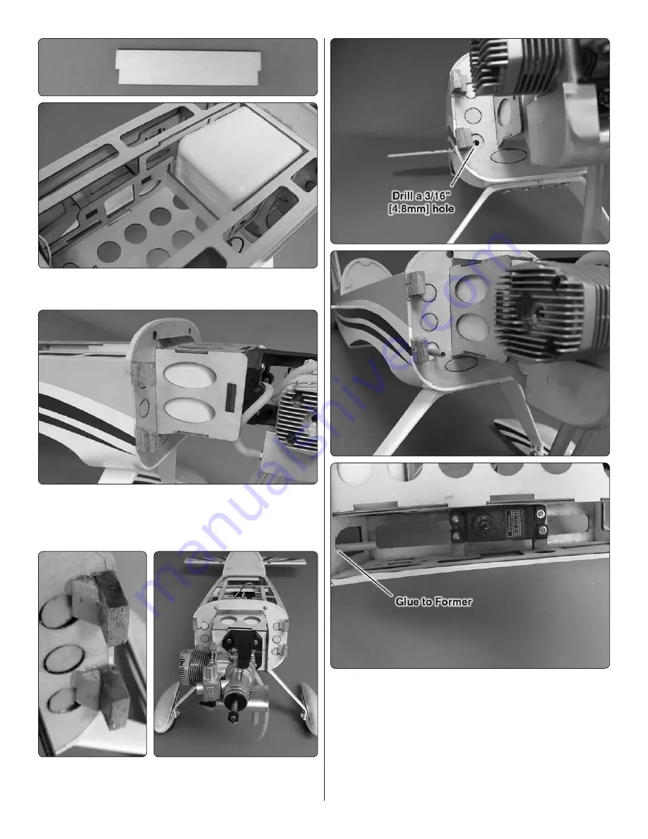
9. Locate the plywood fuel tank stop. Glue it in place in 

the slots in the fuselage just behind the fuel tank.

❏ 

10. Glue four 1/4" x 5/8" x 5/8" [6mm x15mm x15mm] cowl 

mounting blocks to the fuselage, two on each side as shown 
in the photo. The block should be mounted fl ush to the side 
of the fuselage.


❏ 

11. Locate the 1/4" x1/4" x 2" [6mm x 6mm x 51mm] triangle 

stock. Cut off four 5/8" lengths and epoxy them to the fi rewall 
and the cowl mounting blocks as shown.

❏ 

12. Drill a 3/16" [4.8mm] hole through the fi rewall in line 

with the engine throttle arm and the throttle servo inside of 
the fuselage. Cut the plastic 12" [305mm] pushrod tube to a 
length of 4" [102mm]. Insert it into the hole, passing through 
the fi rewall into the fuselage. Glue the tube to the fi rewall and 
the former inside of the fuselage.

Содержание F1 Rocket Evo

Страница 1: ...user assembled product the user accepts all resulting liability If the buyer is not prepared to accept the liability associated with the use of this product the buyer is advised to return this kit im...

Страница 2: ...ou must assemble the model according to the instructions Do not alter or modify the model as doing so may result in an unsafe or unflyable model In a few cases the instructions may differ slightly fro...

Страница 3: ...o ElectriFly 3S 11 1 3200 mAh 25C Lithium Polymer Batteries Using these two batteries in series will require the use of the GPMM 3143 ElectriFly Series 2 Deans male Ultra 1 Deans Female Ultra Adapter...

Страница 4: ...te purchased separately MonoKote is packaged in six foot rolls but some hobby shops also sell it by the foot If only a small piece of MonoKote is needed for a minor patch perhaps a fellow modeler woul...

Страница 5: ...son contact Product Support by e mail at productsupport greatplanes com or by telephone at 217 398 8970 Order No Description Fuselage Wing Tail Surfaces Cowl Hatch Landing Gear Wheel Pants Spinner EP...

Страница 6: ...de for the installation of the aileron servo mounting blocks Use epoxy to glue the 3 4 x 3 4 x 5 16 19x19x8mm hardwood servo mounting blocks to the inside of the hatch cover Set the cover aside to all...

Страница 7: ...sher head wood screw into each hole you drilled and back it out Apply a drop of thin CA glue into each hole to harden the wood When the CA glue has dried thread a 5 64 x 3 8 2 x 10mm washer head screw...

Страница 8: ...hole at the trailing edge of the root rib of the right wing panel Half of the pin should be inserted into the wing Use a paper towel dampened with denatured alcohol to wipe away any excess epoxy 2 Exa...

Страница 9: ...ring from the stab The tip of the soldering iron doesn t have to be sharp but a fine tip does work best Allow the iron to heat fully Use a straightedge to guide the soldering iron at a rate that will...

Страница 10: ...tab into the fuselage View the model and confirm that the stab is parallel with the wing panels If not use a weight on one side of the stab or tape to bring the stab parallel Lightly sanding the stab...

Страница 11: ...tly coat both sides of the nylon tab with epoxy and fit the fin and rudder to the fuselage Allow the glue to harden before moving on to the next step 5 Temporarily install the tail wheel two 3 32 2 7m...

Страница 12: ...screw against the axle Be sure the set screw is tightened against the flat spot on the end of the axle 4 Slide the wheel pant over the wheel and secure the wheel pant to the landing gear with two 2 56...

Страница 13: ...Be sure to harden the screw holes with thin CA as was done with the aileron servos Cut three arms from two four armed servo arms Center the servos with your radio system and install them onto the ser...

Страница 14: ...Though the engine has not been installed yet determine which side of the fuselage to install the throttle servo based on the location of the throttle arm on the engine Install the servo as shown using...

Страница 15: ...t side mounted to the firewall so that the engine head will be on the right side Test fit your engine between the mount halves Slide the mount halves against the sides of the engine and finish tighten...

Страница 16: ...lage 11 Locate the 1 4 x1 4 x 2 6mm x 6mm x 51mm triangle stock Cut off four 5 8 lengths and epoxy them to the firewall and the cowl mounting blocks as shown 12 Drill a 3 16 4 8mm hole through the fir...

Страница 17: ...cure it with a nylon FasLink If you are installing the glow engine skip ahead to Install the Cowl Install the Electric Motor 1 Locate the wood components of the electric motor box Because of the way t...

Страница 18: ...6mm x 51mm triangle stock Cut off four 5 8 lengths and epoxy them to the firewall and the cowl mounting blocks as shown 8 Turn the fuselage over and mount the speed control to the bottom of the motor...

Страница 19: ...llowing steps Those of you installing the glow option have very little need to access this area of the fuselage after the construction is complete so we recommend you complete the following steps 1 Re...

Страница 20: ...move the cowl Apply a couple drops of thin CA into the holes in the cowl mounting blocks to harden the threads Allow the glue to fully cure before re installing the screws 4 Re install the carburetor...

Страница 21: ...is nose heavy you may wish to consider the optional mounting position shown in step 2 2 Insert the included Velcro strap through the slots in the fuselage Place a piece of R C foam under the receiver...

Страница 22: ...h 3 Position decal on the model where desired Holding the decal down use a paper towel to wipe most of the water away 4 Use a piece of soft balsa or something similar to squeegee remaining water from...

Страница 23: ...he control surfaces FULL THROTTLE RUDDER MOVES RIGHT ELEVATOR MOVES DOWN RIGHT AILERON MOVES UP LEFT AILERON MOVES DOWN 4 CHANNEL RADIO SET UP STANDARD MODE 2 3 Make certain that the control surfaces...

Страница 24: ...or the C G center of gravity balance point can have the greatest effect on how a model flies and could determine whether or not your first flight will be successful If you value your model and wish to...

Страница 25: ...t and the bottom of the fuse under the TE of the fin Do this several times 2 If one wing always drops when you lift the model it means that side is heavy Balance the airplane by adding weight to the o...

Страница 26: ...manufacturer s recommendations Do not use hands fingers or any other body part to try to stop the engine To stop a gasoline powered engine an on off switch should be connected to the engine coil Do n...

Страница 27: ...the screws included with your radio 13 Secure connections between servo wires and Y connectors or servo extensions and the connection between your battery pack and the on off switch with vinyl tape h...

Страница 28: ...ane get ahead of your skills Fly the airplane at a speed you are comfortable with After flying around for a while and while still at a safe altitude with plenty of fuel practice slow flight and execut...

Отзывы: