background image

6

Hook Up the Elevator and Rudder

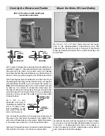
Refer to this picture while hooking up

the elevator and rudder.

5/16"

[8mm]

1/4"

[6.5mm]

RUDDER

ELEVATOR

 1. In order to achieve the correct elevator and rudder throws 

specifi ed on page 11, the pushrods need to be connected to 
the servo arms as shown. If your servo arms don’t already 
have holes that are the correct distance out, drill new holes in 
the servo arms you will be using and cut off the unused arms.

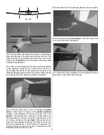
 2. Place the elevator and rudder servos in the servo tray in 

the fuselage. Temporarily connect the servos to your receiver 
with the battery and ESC so you can power the system up. 

Note:

 With 3-channel models such as this (where there are 

no ailerons), it is common to connect the rudder servo into 
the “aileron” channel in the receiver. This way, the right stick 
will still be used for turning the model. If it is your preference 
however, you may connect the rudder servo into the rudder 
channel instead.

 3. Turn on your 

transmitter and plug in 
the battery and center the 
servos. Connect screw-
lock connectors to the 
servo arms. Then fi t the 
arms onto the servos.

 4. Connect the pushrods to the screw-lock connectors on 

the servo arms, and center the elevator and rudder. Then, 
with a drop of threadlocker on the screws, tighten the screws 
in the screw-lock connectors to lock the pushrods down.

 5. Use CA to glue the servos into position. Install the screws 

that hold the servo arms onto the servo output shafts.

Mount the Motor, ESC and Battery

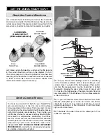
 1. Cut a 1-1/4" x 1/2" [32 x 12mm] strip from the “rough” 

side of the adhesive-backed hook-and-loop strip that 
came with this kit. Stick the strip to the back of the fi rewall 
brace just behind the fi rewall. This is where the battery will 
be mounted.


 2. Mount the motor with the included (3) 2 x 5mm Phillips 

wood screws. Use the included adhesive-backed hook-and-
loop strips, or double-sided foam tape (not included), to 
mount the receiver and ESC. Guide excess wiring behind 
each component inside the fuselage.

SERVO ARM

SCREW-LOCK

CONNECTOR

NYLON

RETAINER

Содержание ElectriFly Sopwith Pup

Страница 1: ...ly in new and unused condition to the place of purchase To make a warranty claim send the defective part or item to Hobby Services at the address below Hobby Services 3002 N Apollo Dr Suite 1 Champaig...

Страница 2: ...important things you can do to preserve the radio controlled aircraft hobby are to avoid flying near full scale aircraft and avoid flying near or over groups of people PROTECT YOUR MODEL YOURSELF OTH...

Страница 3: ...00 Finally a suitable propeller such as a Great Planes 8 x 6 Power Flow Slo Flyer Electric Propeller GPMQ6610 qty 2 will also be required Radio Equipment The ElectriFly Sopwith Pup is designed to fly...

Страница 4: ...the bottom These perforations will strengthen the glue bond between the struts and wing 3 Test fit the bottom wing to the fuselage When satisfied with the fit apply a generous bead of foam safe CA to...

Страница 5: ...o fit one of the plywood control horns to the Z bend on the end of the elevator pushrod already in the fuselage Fit the horn into the slot in the bottom of the elevator Use a sharp 11 hobby knife to c...

Страница 6: ...o the rudder channel instead 3 Turn on your transmitter and plug in the battery and center the servos Connect screw lock connectors to the servo arms Then fit the arms onto the servos 4 Connect the pu...

Страница 7: ...so the cabanes fit easily then glue them into position 2 Test fit the top wing to the cabanes by fitting the tabs of the cabanes into the notches in the wing View the model from the bottom to make ce...

Страница 8: ...the pilot into position Attach the Cowl and Add the Decals 1 Before attaching the cowl connect your battery and turn on the radio and momentarily power up the motor to make sure it is turning the corr...

Страница 9: ...add a drop of thin foam safe CA and cut off any excess line 3 Turn the fuselage over Using care to keep the lines just tight enough so they don t sag but not so tight as to introduce any warp into th...

Страница 10: ...provides you with the best chance for success and enjoyable first flights that should be surprise free Additionally the throws and C G shown are true real data which will allow the model to perform in...

Страница 11: ...check the C G after the weight has been installed PREFLIGHT Charge the Batteries Follow the battery charging instructions that came with your radio control system to charge the transmitter batteries Y...

Страница 12: ...ish a gentle climb Once at altitude the first priority will be to trim the elevator and rudder so the model flies straight and level Once the model has been trimmed continue to fly around for a few mi...

Отзывы: