background image

❏ 

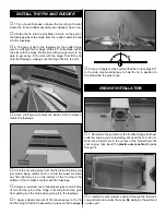
5. Cut a piece of foam the size of the bottom of the fuel

tank. Place this foam inside the fuel tank compartment. Then
insert the tank into the fuel tank compartment.

❏ 

6. Attach a piece of silicone fuel tubing to each of the fuel

tank fittings. Pass the lines through the hole in the firewall.
Connect the lines to the engine. The line attached to the fuel
clunk attaches to the carburetor and the other to the pressure
fitting on the muffler. Note: Refer to the sketch at Step 3 to
see exact fuel line connection.

❏ 

7. Cut another piece of foam and place it on top of the fuel

tank, then reinstall the fuel compartment hatch to the fuselage.

❏ 

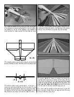
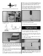
1. Cut away the covering in the wing to reveal the openings

for the two servos as shown in the above photograph.

❏ 

2. Trial fit the servo tray into the opening in the bottom of

the wing. It should fit between the rib in each half of the wing.
Trim the tray as needed to fit into the wing.

❏ 

2. Measure down from the surface of the wing 5/8"

[15.9mm]. On that mark draw a line that is parallel to the
bottom of the wing. Do this on the rib on both the right and
left wing panel.

❏ 

3. Locate the two hardwood landing gear rails. Using 

6-minute epoxy, glue the rails in place on the bottom of the
lines you have drawn.

❏ 

4. After the glue has cured, glue the servo tray to the rails

with 6-minute epoxy. Be sure the side by side servo openings 
in the tray match up with the two servo cutouts in the wing.

❏ 

5. Install a 6" [150mm] servo extension onto the end of

two servos. (Hint: Tape the connectors together to insure the
extension does not unplug from the servo.)

❏ ❏ 

6. Install one servo into the aileron servo bay in the

right wing, feeding the servo wire through the wing ribs,
exiting into the radio compartment.

❏ ❏ 

7. Drill four 1/16" [1.6mm] holes in the servo mounting

tray for the servo screws. Note: Installing the screws without
drilling the holes may result in the plywood servo tray splitting.

RADIO INSTALLATION

10

Содержание Dazzler ARF

Страница 1: ...sembly or material used for final assembly no liability shall be assumed nor accepted for any damage resulting from the use by the user of the final user assembled product By the act of using the user...

Страница 2: ...orking model that functions very much like a full size airplane Because of its performance capabilities the Dazzler if not assembled and operated correctly could possibly cause injury to yourself or s...

Страница 3: ...ottle servo and throttle pushrod exit on the firewall so plan ahead Radio Equipment The Dazzler will require a good 4 channel radio such as the Futaba 4YF FUTJ40 with five servos If you are the type o...

Страница 4: ...nt 4 1mm screws Pre installed in fuel tank hatch 2 Aluminum straps mounting engine to engine mount 4 8 32 bolts for mounting engine to the engine mounting straps and engine mount 8 8 32 nuts for mount...

Страница 5: ...ogether while the glue cures 3 After the glue has cured apply the self adhesive wing tape to the wing joint 1 Trim away the covering on the wing saddle 2 Locate six triangle wood blocks Glue them in p...

Страница 6: ...over and mark the location of the fuselage on the top of the wing 7 Cut away a 1 2 13mm strip of the film from the wing Be sure the cut is inside of the line Important Use only enough pressure to cut...

Страница 7: ...h side of the stab saddle to correct the problem Work slowly and check the alignment often 5 When you are satisfied with the position of the stab use a felt tip pen to mark the sides of the fuselage o...

Страница 8: ...y be on the bottom of the fin where the bottom of the fin makes contact with the fuselage 6 Apply a small amount of petroleum jelly or small drop of oil onto the joint of the hinge This will prevent t...

Страница 9: ...tic pushrod extends through the firewall 1 3 4 44mm then glue it in place to the firewall 7 Install the braided cable into the outer plastic pushrod 8 Attach the cable to the throttle barrel with the...

Страница 10: ...f of the wing Trim the tray as needed to fit into the wing 2 Measure down from the surface of the wing 5 8 15 9mm On that mark draw a line that is parallel to the bottom of the wing Do this on the rib...

Страница 11: ...er be connected by a Y harness or if you have a computer radio with channel assignments you can plug each servo into a separate channel See your radio instruction manual for the set up procedure 13 Lo...

Страница 12: ...rews should pass through the horn and the rudder then screw into the control horn mounting plate on the opposite side of the rudder 23 Attach the clevis to the outermost hole in the horn then slide th...

Страница 13: ...nto the threaded end of the pushrod 14 turns 34 Center the aileron Make a mark on the solid wire pushrod where it lines up with the outermost hole in the servo arm Make a 90 degree bend at the mark Cu...

Страница 14: ...the main landing gear wire Lock it in place onto the wire 1 25mm from the end of the wire 6 Insert a foam wheel onto the wire followed by another wheel collar Tighten the wheel collar in place on the...

Страница 15: ...row outward will increase it Note Throws are measured at the widest part of the elevators rudder and ailerons We recommend the following control surface throws as a starting point Low Rate High Rate E...

Страница 16: ...must add weight to the nose to balance the model If the nose drops it is nose heavy and you must add weight to the tail to balance the model Note Nose weight may be easily installed by using a spinne...

Страница 17: ...e doing Repeat this test with the engine running at various speeds with a helper holding the model If the control surfaces are not always responding correctly do not fly Find and correct the problem f...

Страница 18: ...p to the high rate control throws and you will have a very responsive fun fly type of plane The Dazzler has no bad ground handling characteristics Simply line up on the runway advance the throttle slo...

Страница 19: ...be almost hands off Without touching any other control on the transmitter suddenly chop the throttle Did the nose drop When you add power again did the nose pitch up a bit If so you need some down thr...

Страница 20: ...e loops D Yaws right on insides and left on outside loops E Yaws left in insides and right on outside loops A Wings are level and plane falls to either side randomly B Falls off to left in loops Worse...

Отзывы: