❏ ❏
8. Install the servo using the hardware provided from
the radio manufacturer.
❏ ❏
9. Repeat steps 6-8 for the left wing.
❏
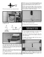
10. Install three servos into the servo tray using the
hardware provided by the manufacturer. Position the servos
as shown in the photograph.
❏
11. The open area in front of the servo tray is where you
will locate the battery and receiver. Cut a piece of the foam
pad and fit it in the opening. Lay the battery on the foam. Cut
another piece of the foam pad and lay it on top of the battery,
then place the receiver on top of the foam. Optional:
Depending on the size of the battery and receiver you may
choose to put them on end, side by side.
❏
12. Connect all of your servo leads into the receiver as
recommended by the radio manufacturer. The aileron servos
can either be connected by a Y-harness or if you have a
computer radio with channel assignments you can plug
each servo into a separate channel. See your radio
instruction manual for the set-up procedure.
❏
13. Locate the radio compartment cover. Measure
5-1/8" [128mm] from the back edge of the cover towards the
center of the cover and make a mark. Draw a line across the
width of the cover. This is the center line for the switch and
charging jack installation. It is important that this line falls
between the servo tray and the cavity for the battery and
receiver or there may not be enough room for the switch and
charge jack. Before cutting the location for them, visually
check to be sure the line falls in the correct location.
❏
14. Cut the openings and install the switch and charge jack.
❏
15. Locate four 1/4" x 9/16" x 9/16" [6 x 14 x14mm]
hardwood blocks. Glue them in each corner on the inside
of the radio compartment cover.
❏
16. Connect the battery to the switch harness and receiver.
11


