2019-06-12
401-705M
YP3025A
Operating Instructions
48
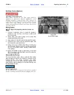
Weight Transfer Operation (Option)
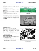
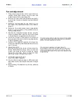
This option provides a control valve
, plumbed into the
hydraulic drive circuit, and a cylinder for each wing.
Up to 1000 pounds (450 kg) of mainframe weight may be
transferred to each wing when oil is being supplied to the
hydraulic drive circuit.
Once set, the circuit usually requires little adjustment in
normal field operations. To set the circuit:
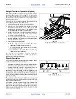
1. Unfold and lower the planter in field conditions.
2. Supply oil to the hydraulic drive circuit (or operate
the PTO at field rpm if using a PTO pump that
supplies the hydraulic drive). The hydraulic drive
motor itself does not need to be operated.
3. Loosen the lock disc at the valve block. Adjust the
knob until the gauge
reads approximately
1000 psi. Tighten the lock disc.
4. Lower the planter. Engage the hydraulic drive (with
seeding disabled) Pull forward at normal field speed
for a short distance. Stop.
5. Check that the wings are level.
See page 16 and page 170 for important information
about movements without a suitable tractor. See
page 129 for ordering information.
Clutch Operation
The YP3025A Planter has drive system clutches, which
enable or disable row unit meter drive:
•
(standard) an electric clutch for each planter section
(left wing, center, tight wing; 3 clutches total), or
•
(Swath Command option) a pneumatic clutch for
each row, or, on twin row, for each row pair.
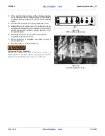
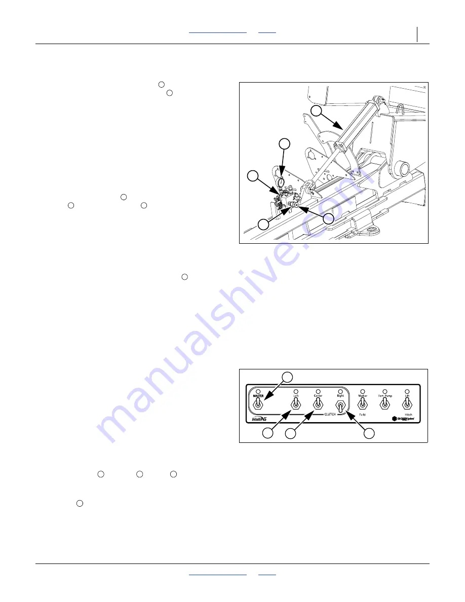
Switches on the CFM provide control of clutches for the
entire planter, or for each planter section. This control is
in addition to that provided by the lift switch (all rows
on/off), and the Swath Command option (arbitrary sets of
clutches ON/OFF).
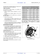
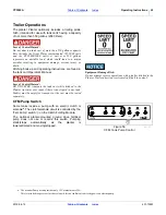
The switches Left / Center / Right correspond to
the left wing row units, center section row units and right
wing row units respectively.
The Master switch controls all row units, regardless of
drive type. For all switches, “OFF” (down) removes
power from the clutch, disengaging that set of row units.
When any switch (plus Master) is ON, the LED for that
switch illuminates steadily.
•
If the wings ends are lower than the center,
decrease the pressure at the valve .
•
If the wing ends are higher than the center,
increase the pressure.
A relief valve in the valve block prevents any
damage from over-pressure.
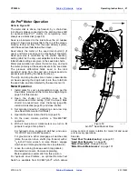
Figure 51
Weight Transfer Valve and Cylinder
36421
2
1
4
3
5
Figure 52
CFM: Clutch Switches
26120
1
2
3
4

