background image

2019-06-12

Table of Contents

Index

401-705M

YP3025A

Table of Contents

Index

Operating Instructions

40

Changing the Seed Box or Hopper

The YP3025APlanter accepts the Great Plains 82 bu.

hopper,150 bu.

a

 hopper, or bulk seed boxes that meet

the Pioneer

b

 ProBox® specification.

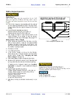
Tipping and Overload Hazard:

Place or remove a hopper only when empty. A full hopper can
weigh between 5000 and 10000 lbs (2700-4500 kg), which is

above the lifting and balance capability of most tractors and

farm forklifts.

1. Move the Planter to an area of level ground and 

sufficient room to maneuver a tractor or fork-loader.

2. Unhitch tank cart if present.

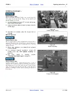
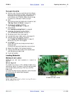
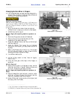
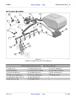
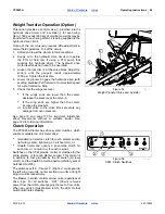
Refer to Figure 42 (depicting identical operation on 

YP40)

3. Disconnect hopper level sensor (if installed).
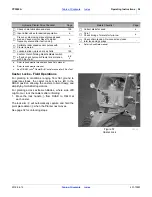
4. Remove the pin

 securing the left end of the 

walkboard to the ladder assembly.

5. Swing the walkboard open, and secure it at full open

with the keeper

.

6. Raise the Planter. This causes the rear transport

wheels to move forward, providing closer access for

the lifter.

7. Back up the Planter about 3 feet (1 m). This causes

the rear transport wheels to caster forward, further

reducing the reach required for lifting.

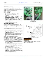
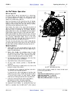
8. Turn off the seed box fan.

9. Put the towing tractor in Park. Shut off engine.

Remove key.

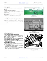
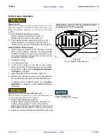
10. Close the slide gate at the base of the hopper or

seed box.

Refer to Figure 43

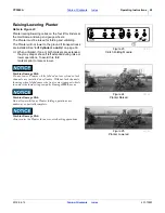
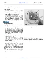
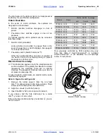
11. Remove the two pins

, at opposite corners, used to

retain the seed box or hopper. Remove these pins

even if no container is presently mounted.

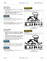
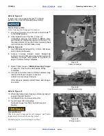
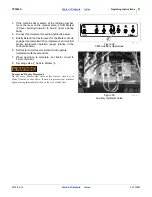
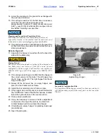
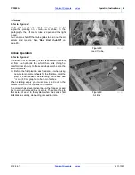
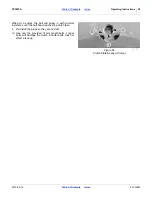
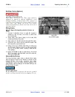
Refer to Figure 44 (depicting identical operation on 

YP24)

12. Align the lifting forks with the slots in the rear of the

seed box or hopper. Slowly drive forward until the

forks are completely under the container.

13. Slowly lift the seed container above the bracket, and

back away from the Planter.

a. The 150 bu. hopper is incompatible with on-board fertilizer tanks.
b. PROBOX® is a registered trademark of Pioneer Hi-Bred International, Inc.

2

3

Figure 42

 Walkboard Pin and Keeper

29312

1

1

Figure 43

 Seed Box Lock Pins

29267

2

3

Figure 44

Removing/Mounting Hopper

26121

1

Содержание YP3025A

Страница 1: ...30 Foot 3 Section Yield Pro Planter with Air Pro Seed Meters Read the operator manual entirely When you see this symbol the subsequent instructions and warnings are serious follow without exception Yo...

Страница 2: ...red the weights and measurements are no longer accurate for your machine Update the record by adding the machine weight and measurements with the option s weight and measurements Dealer Contact Inform...

Страница 3: ...o Planter 16 Hydraulic Hose Hookup 16 If Weight Transfer is Installed 16 Electrical Hookup 18 Hitching with 3 Point 18 Hitching with Hydraulic Tongue Option 19 Raising Lowering Tongue 19 Parking Stand...

Страница 4: ...98 Air Box Clean Out 98 Air System Clean Out 98 Meter Clean Out 99 Funnel Conversion 99 Alternate Meter Clean Out 100 Seed Tube Clean Out 100 Meter Brush Maintenance 101 Meter Brush Replacement 102 Se...

Страница 5: ...d will result in death or serious injury This signal word is limited to the most extreme situations typically for machine components that for functional purposes cannot be guarded WARNING indicates a...

Страница 6: ...fire Store or dispose of unused chemicals as specified by chemical manufacturer Use A Safety Chain Optional hydraulic hitch only 3 Point has no chain Use a safety chain to help control drawn machinery...

Страница 7: ...erous and should be performed by trained personnel using correct tools and equipment When inflating tires use a clip on chuck and extension hose long enough for you to stand to one side not in front o...

Страница 8: ...t allow adequate control of steering and stopping Reduce speed if towed load is not equipped with brakes Comply with state and local laws Do not tow an implement that when fully loaded weighs more tha...

Страница 9: ...on Planter Inspect all parts Make sure parts are in good condition and installed properly Remove buildup of grease oil or debris Remove all tools and unused parts from Planter before operation Safety...

Страница 10: ...s clean and legible Replace all damaged or missing decals Order new decals from your Great Plains dealer Refer to this section for proper decal placement When ordering new parts or components also req...

Страница 11: ...of axle above Red reflectors two total Amber Reflectors 838 265C On the front of the center section front lower tool bars on the rear of the wing tool bars and on the sides of the seed box frame six...

Страница 12: ...ents Index Important Safety Information 8 Danger Crushing Hazard 818 590C Top center of 3 point hitch one total not present with hydraulic tongue option Danger Electrocution Hazard 838 599C One each s...

Страница 13: ...ce wing caster weldments On side face of rear axle weldment eight total Warning Speed 818 188C On left side of tongue near hitch one total Warning High Pressure Fluid 818 339C On side of tongue at hit...

Страница 14: ...ety Information 10 Warning Pinch Shear Hazard 818 579C Front and rear faces of inner marker arms four total Warning Overhead Marker 818 580C Front and rear faces of inner marker arms four total Cautio...

Страница 15: ...ar transport tire on outside rim each gauge wheel 4 total 31395 31395 31395 31417 WARNING Cancer and Reproductive Harm www P65Warnings ca gov Read Owner s Manual before using machine Stand clear when...

Страница 16: ...ered Document Family Figure 1 planter Planter 31420 U D F B L R L R YP3025A 1230 12 Row 30 inch YP3025A 1270 12 Row 70 cm YP3025A 16TR36 16 Row 8 Twin 36 inch pairs YP3025A 1820 18 Row 20 inch YP3025A...

Страница 17: ...this manual are determined by facing the direction the machine will travel while in use unless otherwise stated An orientation rose in some line art illustrations shows the directions of Up Back Left...

Страница 18: ...ollowing actions first 1 Discuss the matter with your dealership service manager Make sure they are aware of any problems so they can assist you 2 If you are still unsatisfied seek out the owner or ge...

Страница 19: ...or page 173 Post Delivery Seasonal Setup On initial delivery use with a new tractor and seasonally check and as necessary complete these items before continuing to the routine setup items Bleed hydrau...

Страница 20: ...hoses are color coded handle grips to help you hookup hoses to your tractor outlets Hoses that go to the same remote valve are marked with the same color If Weight Transfer is Installed If the option...

Страница 21: ...e same remote valve are marked with the same color tie Refer to Figure 5 To distinguish hoses on the same hydraulic circuit refer to hose label The hose under an extended cylinder symbol feeds a cylin...

Страница 22: ...ake connections prior to Planter movement Some Planter hydraulic circuits are under monitor control Hitching with 3 Point Refer to Figure 7 1 If the Planter is model YP3025A 2415 Even Row 15 inch chec...

Страница 23: ...Extend the Hitch Lift circuit to raise the hydraulic tongue just enough to relieve pressure from the parking stand 12 Remove and store main tongue parking stand See Store Main Parking Stand on page 2...

Страница 24: ...positional under the hitch and insert the removed pin at hole under the stand Refer to Figure 10 2 Adjust the top link of a 3 point long enough so the ball swivel does not bottom out when fully raised...

Страница 25: ...ght inlets Gauge line Tank cart with 3 line pumped tank and 1 line gravity tank planter Planter w Type 2 and Type 3 Manifolds Ground Drive Pump Planter Inlet Left Type 3 Center Type 3 Right Type 3 Typ...

Страница 26: ...ted in tongue bolt holes Tractor 3 point control must be in Depth Control mode and not Draft Control mode For hydraulic tongue Note the scale reading on the tongue for this height Re set the tongue he...

Страница 27: ...6 Adjust the cams until depth and closure are ideal If the ideal setting seems to be in between two notch values use the higher setting Rows in tracks may be higher still 7 Engage the Row Pro system...

Страница 28: ...e 15 For YP3025A planters 1 Remove clevis pin from storage hole 2 Release the lock arm lift handle to lift ground wheel up to position it in between lock arm 3 Secure with pin clevis and cotter pin Ac...

Страница 29: ...s Refer to Figure 17 1 Wing locks Hooks on the tongue engage locks on the wings to prevent unfolding in transport Tongue must be raised to engage release See page 27 2 Lift cylinder lock channels Thes...

Страница 30: ...not unfold with planter lowered or machine damage will result Unfold only with markers resting in transport cradles Unfold only if hydraulics are bled free of air and fully charged with hydraulic oil...

Страница 31: ...locked the pull bar system experiences excess loads The openers may be damaged by not tracking straight forward 11 When fully unfolded set Marker Fold hydraulic circuit to Neutral 12 For imminent lowe...

Страница 32: ...they may drag or shove if left extended during raise or lower operations To avoid this fold markers prior to raise or lower Machine Damage Risk Do not lower Planter while folded unless cylinder lock c...

Страница 33: ...e the locks See Raising Planter on page 29 and Lift Cylinder Lock Up on page 30 2 If equipped with hydraulic hitch set the Lift Hitch switch to LIFT On 3 point hitch this switch has no function and th...

Страница 34: ...letely and hold the hydraulic lever or switch in Extend for several seconds after the Planter reaches full elevation or until all cylinders are fully extended 2 When all cylinders are fully extended m...

Страница 35: ...ent Do not allow anyone to be on or near the Planter during folding Stay clear of the wing sweep arcs The sweep arcs of the wings have numerous pinch and crush points in the mechanism Coulters and row...

Страница 36: ...cuit to fold wings Sequence begins with releasing of tongue latch Refer to Figure 22 on page 27 Before folding completes 9 Raise Planter tongue Raising Lowering Tongue on page 19 This must be done bef...

Страница 37: ...llon tank cart hitched to the Planter in train could add another 3000 pounds 1400kg empty The tractor unit MUST be rated for the load If the tractor is not rated for at least 42000 pounds calculate or...

Страница 38: ...3025A 1230 16TR36 1820 2315 2415 24TR 3610 1270 2335 24TR70 Configuration Pounds Kilograms 21900 22700 23000 24400 24600 24700 27400 9900 11100 11200 23500 24500 25000 26600 26900 26900 30400 10600 12...

Страница 39: ...e page 35 If Planter wings are unfolded fold them See Folding the YP3025A Planter on page 31 Make sure wing locks are engaged 3 point hitch Lower hitch fully to ensure wings remain locked Hydraulic hi...

Страница 40: ...iliary Hydraulics Refer to Figure 37 Figure 38 and Figure 39 The planter Planter includes as standard equipment an auxiliary hydraulic circuit intended to power a seed auger for loading bulk hoppers T...

Страница 41: ...switch on implement and confirm proper implement operation auger rotation in the correct direction 6 Set tractor circuit lever to Extend and operate implement with local controls 7 When operation is...

Страница 42: ...ractor in Park 3 Turn off seed box fan 4 If the 82 bu hopper is not yet on the Planter dismount any box or hopper present and mount the empty 82 bu hopper See Changing the Seed Box or Hopper on page 4...

Страница 43: ...ubricant to the pail Mix and pour into air box before mounting hopper 2 Put tractor in Park 3 Turn off seed box fan 4 If the 150 bu hopper is not yet on the Planter dismount any box or hopper present...

Страница 44: ...auses the rear transport wheels to move forward providing closer access for the lifter 7 Back up the Planter about 3 feet 1 m This causes the rear transport wheels to caster forward further reducing t...

Страница 45: ...box Make sure your tractor or fork lift is rated for and configured to lift the weight A full seed box can weight over 2500 lbs 1134 kg a full 82 bu hopper over 5000 lbs 2270 kg 18 If mounting a seed...

Страница 46: ...ter Split Air Manifold Pressure Sensor Chamber Row Pressurizing Tubes Servo Controlled Vane Feedback Signal Line Row Unit Seed Tube WSMT Servo Programming Air Box Seed Manifold IntelliAg Console Prior...

Страница 47: ...delivery air while retaining the delivered seeds 2 It is a passive control gate for bulk seed delivery It takes about a minute to initially fill the meters Separate pressurization tubes provide the a...

Страница 48: ...rn port The unusual size aids in ensuring correct connection so that the motor return line handles high volume at low back pressure ensuring full motor performance 3 Connect the motor inlet line to a...

Страница 49: ...fill meters During FILL METER all air is routed to the air box and none to the meter pressurization system The monitor has a level sensor below the hopper or seed box to warn when seed box is empty T...

Страница 50: ...lent air from the hydraulic fan which then exits through a manifold not shown to the seed tubes which serve the row unit meters Before the first planting each season or when using new meters or meter...

Страница 51: ...r Meter Operation 1 Install disks for your crop population range per the Seed Rate manual and the instructions beginning on page 78 of this manual 2 Open the shutter at planting rows to the recommende...

Страница 52: ...e tractor See page 129 for ordering information Clutch Operation The YP3025A Planter has drive system clutches which enable or disable row unit meter drive standard an electric clutch for each planter...

Страница 53: ...ctric clutches The pneumatic clutches lock up on loss of air pressure see page 49 In case of electric clutch failure an electric clutch can be mechanically engaged Refer to Figure 53 and Figure 54 1 R...

Страница 54: ...cutout the bolt will screw in with minimal resistance until the bolt head reaches the clutch face 4 Re install the plugs so they are not lost Use only the provided 14 mm length bolts Longer bolts wil...

Страница 55: ...fore the pump 3 Open valves at each tank and at quick fill coupler 4 Fill tanks then close valve at quick fill coupler and disconnect the nurse tank hose Always close valve at filter when filling or s...

Страница 56: ...DO NOT EVER transport the tank cart while hitched to the Planter in train over roads if there is any liquid in any tank Tank s must be empty for transport or the cart must be towed separately CFM Pump...

Страница 57: ...ned on to correct rows 46 No air leaks except from seed box Hose routings no sags no pinches check wing folded field positions Hoses fully connected to meters and locked Row Units Checklist Page Prese...

Страница 58: ...raulic Planter Drive Checklist Page Check chain lubrication and slack 126 Input initial values for desired population a Pre run system using manual ground speed mode on seed monitor Reset to digital f...

Страница 59: ...egrated with the DICKEY john seed monitor set the Fert Pump switch on the Clutch Folding Module to ON 52 7 In the CLUTCH cluster of the Clutch Folding Module set all switches including Master to ON 48...

Страница 60: ...n the sequence valve body Excessive folding speed may damage markers See Dual Marker Speed Adjustment on page 171 Marker Unfold one side Refer to Figure 59 and Figure 60 depicting identical operation...

Страница 61: ...l to Retract Hold until marker is folded 2 Set circuit control to neutral Unusual Marker Operations Both Sides Unfolded With both markers in their cradles Unfold either side and when completely deploy...

Страница 62: ...is Planter manual part number 401 627B contains sampling instructions Short Term Parking 1 Fold markers See Folding the Markers on page 57 2 Choose a location with level firm ground Do not unhitch on...

Страница 63: ...ease to exposed cylinder rods to prevent rust 11 Option Flush fertilizer lines if present Flush system with RV anti freeze if there is any chance of freezing prior to next implement use 12 Option Empt...

Страница 64: ...ed Rate manual Marker Adjustments Marker Extension 174 Intended swath spacing Marker Chain Length Adjustment 54 Marker folding operation Dual Marker Speed Adjustment 171 Reliable marker operation Fert...

Страница 65: ...n adjustments assure the rate See the SRM 3 Ground speed calibration Seed monitor rate control and reporting is only as accurate as the speed reported by the radar See the PDC manual 4 Setting seed ra...

Страница 66: ...ealer this rarely needs modification Marker Disk Adjustment Sharp Object Hazard Use caution when making adjustments in this area Marker disks may be sharp Refer to Figure 66 1 To change angle of cut a...

Страница 67: ...n is near suggested value 7 Perform a FILL METER operation for at least one minute see DICKEY john Planter Drill Control user level 1 manual 8 Check for meter fill With fan running put the tractor in...

Страница 68: ...pressurization with the Planter in motion Press the SPLIT AIR softkey on the seed monitor console Wait 5 to 10 seconds for the system to update while you continue planting Continue making small decre...

Страница 69: ...ding equal margin against skips and doubles Record this value for future use Seed Delivery Fan Adjustments Refer to Figure 67 The primary control for seed delivery air is fan rpm The servo vane not sh...

Страница 70: ...The mesh screen size must be compatible with the orifice plates in the distribution system Refer to the Seed Rate manual Great Plains recommends checking with your local agronomist as soil conditions...

Страница 71: ...The T handle sets planting depth by controlling the height of the side gauge wheels relative to the opener discs See Setting Planting Depth on page 73 8 Press Wheel Force Angle Stagger Standard The p...

Страница 72: ...f the wheels are creating a trench into the subsoil down force is too high and needs to be reduced Adjusting Down Force The the planter has the optional Row Pro system set the cam adjusted system to t...

Страница 73: ...prings will be in tension causing more effort and the optional Row Pro system might be active and fighting you The extra force required might also damage tools 2 Install lift cylinder locks 3 Put trac...

Страница 74: ...t with the Planter raised Install lift assist cylinder locks Also check bolt tightness prior to each planting session to avoid down stop slippage To adjust the row cleaner 1 Determine the height adjus...

Страница 75: ...position causes it to contact the ground during the adjustment Be careful around the front end of row units Row cleaner tines and coulter blades may be sharp To adjust coulter depth 1 Determine the p...

Страница 76: ...Operate the planter on some test ground no seed required and verify that the opener blades are in the groove opened by the coulter and that the press wheels are centered over the furrow See Press Whe...

Страница 77: ...r Spacers will need to be reset when blades are replaced The ideal spacing causes the blades to be in contact for about one inch If you insert two pieces of paper between the blades they should slide...

Страница 78: ...are held up At the same time keep side gauge wheels close to opener disks so openers do not plug with soil or trash Wheels should be out far enough so disks and wheels turn freely Refer to Figure 87...

Страница 79: ...N m Adjusting Gauge Wheel Scrapers Refer to Figure 88 bottom view Scrapers are optional and may be useful in moist or sticky soils that tend to accumulate on gauge wheels and reduce intended planting...

Страница 80: ...lugs Re install the seal Seed Inlet Shutter Adjustment Refer to Figure 90 showing the shutter at setting 3 The seed inlet shutter regulates the volume of bulk seed presented to the seed disk The opera...

Страница 81: ...seed monitor Row Failure alarm with a report of the row number Row numbers are counted from the left wing outside row is row 1 Stop and put the tractor in Park Leave the fan running Locate the failed...

Страница 82: ...a disk is first clamped it is normal for the disk hub to be flat with the face of the disk seat only on the inlet rear side The disk fully seats as it first turns This condition eases as the brush fib...

Страница 83: ...disk seat in Figure 94 page 78 so that new disks can seat fully Inspect brushes for excess wear and damage See Meter Brush Maintenance on page 101 5 Inspect removed disks for excess wear and damage S...

Страница 84: ...te Move it to the top position and release the handle into the notch Closing the shutter prevents meter pressurization air from leaking into the bulk seed air system resulting in lower pressures in ad...

Страница 85: ...If you lose a pin the replacement part number is 805 033C 1 Raise the Planter Although this adjustment can be made with the Planter lowered the springs will be in tension and will require more effort...

Страница 86: ...mer lower the planter until the disks of the row units are resting on the ground Keeton Seed Firmer Adjustment The optional Keeton Seed Firmer is an engineered polymer shape that slides down the seed...

Страница 87: ...of the handle Alternatively lift up on the wheel 2 Rotate the handle clockwise handle arm up until the Seed Lok wheel releases at the latch point and falls free 3 While holding the handle up rotate th...

Страница 88: ...in row unit shank components such as the openers High press wheel settings may require an increase in overall row unit down force See page 68 Press Wheel Stagger The factory stagger setting has been f...

Страница 89: ...ise planter and install lift assist cylinder locks See Lift Cylinder Lock Up on page 30 3 Loosen the 3 8 inch hex head bolts and Do not loosen the square head bolts forward of the hex head bolts 4 Tur...

Страница 90: ...ive transmission and range sprocket selections or the population settings on a hydraulic drive unit See also Population Too Low or Population Too High in the troubleshooting charts Yes Go to step 2 2...

Страница 91: ...may include low fan speed seed hose blockage no seed available Y tube closed meter never primed Oversize matter in seed has caused a bridge at the top of the inlet Air back flow is occurring When the...

Страница 92: ...sk skips due to insufficient air pressure Methodically increase the controlled air to the meter See Fan and Adjustment on page 63 Empty pockets on disk skips due to sticky seed treatments not allowing...

Страница 93: ...e to meter pressurization leaving insufficient air for seed delivery Install blank disks and close shutters on unused rows Excess field speed Plant within speed ranges recommended in seed rate charts...

Страница 94: ...d that there are no other obstructions upstream Meter starvation due to bridging above inlet caused by high levels of seed treatment Clear bridge page 77 Increase seed lubricant Skips due to low meter...

Страница 95: ...ed sensor constant Perform speed calibration per DICKEY john monitor manual See page 175 Doubles due to incorrect disk for crop or seed size Use recommended disk for crop and seed size Sticky seeds ex...

Страница 96: ...out of disk pockets Insufficient hydraulic flow to keep fan running at speed required to maintain meter pressurization Check tractor capability against requirements page 145 If sufficient Fold marker...

Страница 97: ...e air leak Check for air leak downstream between box and top of meter All rows fail Lack of seed Fan speed too high Adjust fan speed Extremely high populations may require slightly reduced field speed...

Страница 98: ...to page 106 Uneven seed depth Excessive field speed Reduce field speed Planting conditions too wet Wait until drier weather Incorrect coulter depth setting See coulter manual or set unit mounted coult...

Страница 99: ...plugging between air box and Y tubes Fan too slow Speed up fan Air leaks between air box manifold and splitters Check for leaks and correct as needed Improper hose routing sags or kinks With Planter...

Страница 100: ...tch set to Fold CFM Switch must be set to Marker for Aux to function Set tractor remote circuit to Neutral or Float before switching Marker Aux valve set to Marker Selector valve must be set to Aux Se...

Страница 101: ...small hole can be almost invisible Use paper or cardboard not body parts and wear heavy gloves to check for suspected leaks Escaping fluid under pressure can have sufficient pressure to penetrate the...

Страница 102: ...tied Use gates to regulate seed flow while recovering seed 5 As flow subsides rapidly open and close the slide gate to dislodge seed in the tracks Tap on the sides of the hopper to dislodge residual s...

Страница 103: ...ld all the seed in the meter and inlet up to a closed slide gate The container can be converted into a true funnel for complete system clean out The hoppers are connected to the rows with clamped hose...

Страница 104: ...funnel Refer to Figure 115 17 Clean seed from all brushes shop vac recommended 18 Inspect brushes page 101 19 Rotate funnel clockwise remove and empty 20 For imminent operations Install next seed whee...

Страница 105: ...asing population Finding an occasional cracked seed hung up on a tuft fiber is not uncommon and is not an indicator that brush maintenance is required Merely remove the seed If the strip brushes are w...

Страница 106: ...rush holder 2 Prepare to catch drop brush which will fall lose Slide brush holder left and up to free front edge from under washer Remove brush holder 3 Remove used strip brushes from the holder by sl...

Страница 107: ...n away replace the disk If the seed pockets are worn through or the air ports have enlarged replace the disk Cleaning and Storing Seed Disks Possible Chemical Hazard Wear gloves when washing disks Avo...

Страница 108: ...in the airbox Open the airbox clean out door 4 Remove the inspection port covers from each end of the airbox not shown in figures 5 Use an indelible marker to identify the hoses on seed hose ports 1...

Страница 109: ...nd routine service of the tractor filtration To change the element Refer to Figure 122 1 Unscrew lower canister from filter catching and disposing of used fluid 2 Remove and discard element 3 Install...

Страница 110: ...ore shipping and bleeding should not be required other than to raise fully and hold lever on for one minute or until all cylinders extend fully If it is necessary to further bleed lift system see Lift...

Страница 111: ...id appears at the loosened fittings Set circuit to Neutral and secure fittings 7 Re pin rod ends Fold Cylinder Bleeding Refer to Figure 125 1 Begin with Planter raised and lift cylinder locks installe...

Страница 112: ...er cylinder 7 Retract the circuit until fluid appears at the loosened fittings Set circuit to Neutral Secure fittings 8 Repeat for the other side 9 Re orient gravity pin lock to position noted at step...

Страница 113: ...wing section This should be the same as measured at step 1 above See page 110 for adjustments Wing Leveling Inboard End Wing leveling check adjustment is required prior to first use of the YP3025A Pl...

Страница 114: ...nt serial number B1007W Refer to Figure 131 The YP3025A Planter includes a sensing switch that signals the seed monitor and activates the optional hydraulic meter drive when the Planter is lowered for...

Страница 115: ...he right link connecting the rockshaft and rear axle Although factory preset for typical planting conditions Great Plains recommends adjusting this switch for your exact field conditions and planting...

Страница 116: ...ear units 4 Check for proper alignment by running a string line across back of Planter toward outer ends of wings For proper alignment outside ends of wings should be 0 to 1 4 inch 0 to 6 4 mm ahead o...

Страница 117: ...r of the span deflect the chain in both directions The slack is the distance of the movement 4 Adjust the idlers for ideal slack Chain Clips Whenever mounting a chain make sure the clip at the removab...

Страница 118: ...re rough inspect and replace if necessary 2 Side wheels are preset at the factory Due to normal wear it may become necessary to make adjustments so the wheel remains close to the disk To prevent plugg...

Страница 119: ...o straps Refer to Figure 141 A new 150 bu hopper requires periodic attention to the hopper strap as the hopper initially seats and thereafter due to continued hopper seating and strap stretching Check...

Страница 120: ...son Filter Cleaning 1 Shut off the ball valve at the filter to minimize product spill 2 Unscrew and remove the bottom canister of the filter 3 Wash the filter cartridge with water or replace with new...

Страница 121: ...ing 2 total Type of Lubrication Grease Quantity Until Grease emerges Wing Caster Wing Pivot 1 zerk each of 2 casters 2 total Type of Lubrication Grease Quantity Until grease emerges zerk is located on...

Страница 122: ...ng at wing frame to tool bar joint Type of Lubrication Grease Quantity Until grease emerges Rockshaft to Main Frame 1 zerk each side 2 total Type of Lubrication Grease Quantity Until grease emerges Ro...

Страница 123: ...one each inside end of pins each side Type of Lubrication Grease Quantity Until grease emerges Mainframe to Rear Sub Frame 1 zerk each side 2 total Type of Lubrication Grease Quantity Until grease eme...

Страница 124: ...e zerk each link 2 total Type of Lubrication Grease Quantity Until grease emerges Level Link Both Ends One zerk each link end 4 total Type of Lubrication Grease Quantity Until grease emerges Rear Cast...

Страница 125: ...unit Type of Lubrication Grease Quantity Until grease emerges Marker Joints 2 zerks each marker each wing 4 total Type of Lubrication Grease Quantity Until Grease emerges Fertilizer Pump Bearings Opti...

Страница 126: ...mainframe center section Type of Lubrication Chain Lube Quantity Coat thoroughly Lubricate chains any time there is a chance of moisture and when being stored at the end of the planting season To avo...

Страница 127: ...ntity Coat thoroughly Lubricate chains any time there is a chance of moisture and when being stored at the end of the planting season To avoid clutch slippage prevent chain lube from getting on electr...

Страница 128: ...ntly on a new drill and with new tires Check tire pressures whenever there are planting problems 150 Bu Hopper Straps Option 1 strap each hopper See Hopper Strap Maintenance Option on page 115 for ins...

Страница 129: ...l grease emerges Tongue Latch Type of Lubrication Spray lube Quantity Coat working surfaces Tongue Slide Roller 1 zerk roller end Type of Lubrication Grease Quantity Until grease emerges Wing Transfer...

Страница 130: ...sing damaged tilted or top of piston is visible Measuring the length requires at least partial disassembly of the caster pivot and is not recommended unless there are indications that the piston might...

Страница 131: ...isk Hub 4 bearings 2 each marker Type of Lubrication Grease Quantity Re pack Transport Wheels Wheel Hubs 8 bearings 2 each of 4 wheels Type of Lubrication Grease Quantity Re pack Gauge Wheel Bearings...

Страница 132: ...ronments increase the rate as needed for smooth meter operation Irritation and Chronic Exposure Hazard Wear gloves DO NOT use hands or any part of your body to mix seed lubricant Wear a respirator whe...

Страница 133: ...YP40 44 WEIGHT TRANSFER 411 172A Kits and Couplers Part Number YP30 PTO KIT For model YP3025A 401 946A YP24F PTO HYDRAULIC PUMP KIT For model YP3025AF 411 014A 1 3 4 20 PTO COUPLER 826 777C 1 3 8 21 P...

Страница 134: ...on the YP3025A Planter but may be optionally deleted line item 401 704A for example if all planting is done via GPS navigation If any possible future planting or re sale considerations might require...

Страница 135: ...Type 2 boom has a single inlet and is optimized for use with a Planter mounted ground drive pump The base Type 2 system is plumbed to the on board tanks The 407 243A kit extends it to the rear hitch...

Страница 136: ...07 451M Ground Drive Fertilizer Pump One pump kit integrates with the Type 2 fertilizer manifold system The pump mounts on a wing tool bar and requires a Planter with a 13 8 inch 35 cm or greater sing...

Страница 137: ...407 244A on board 2x200 gallon tanks page 132 or customer provisioned cart a trailer hitch weldment 401 467A page 130 if a cart is used Type 3 Fertilizer Manifold The Type 3 system includes all plumbi...

Страница 138: ...e used for the tanks The hoppers have no other prerequisites on the Planter but you will need a means of top loading seed when the hopper is mounted on the seed box such as an auger connected to the s...

Страница 139: ...d later You will need a means of top loading seed when the hopper is mounted on the seed box such as an auger connected to the standard auxiliary hydraulic ports If added later see installation manual...

Страница 140: ...that you need to update your WSMT software and a non standard CANbus console is in use and a DICKEY john 10 inch Monitor Console is not available The kit includes a USB to CANbus adapter adapter to C...

Страница 141: ...mmand Controller This DICKEY john A5 console supplements the standard DICKEY john IntelliAg console as well as some models of customer provisioned monitors It accepts the GPS coordinate feedb performs...

Страница 142: ...WAAS at 1 5 or 10Hz position update rates 467980458 cable on page 137 provides interface Mount is three 10 mm bolts This receiver is recommended for auto steer and Swath Command applications Row Pro S...

Страница 143: ...or less Description Part Number PIN HITCH 1 X 6 W HAIRPIN 805 033C Single Wheel Coulter Mount Part Number YP3025A 24TR on every row YP3025A 24TR70 on every row 207 108A Double Wheel Coulter Mount Par...

Страница 144: ...Part Number YP3025A 1230 YP3025A 1270 204 552A YP3025A 16TR36 204 551A YP3025A 1820 204 546A YP3025A 2315 on every row YP3025A 2335 on every row 204 534A YP3025A 2415 on every row 204 528A YP3025A 24T...

Страница 145: ...justment as wheel and scraper wear For operations see Adjusting Gauge Wheel Scrapers on page 75 Inside Disk Scrapers When planting in moist or sticky soils these scrapers are useful in preventing buil...

Страница 146: ...794C Corn 24 Cell Medium 837 126C Corn 24 Cell Small Round or Flat 817 795C Corn 40 Cell Large Flat 817 838C Corn 40 Cell Large Round 817 796C Corn 40 Cell Medium 837 127C Corn 40 Cell Small Round or...

Страница 147: ...which include one of three firmers seed flap Keeton or Seed Lok Only one type of seed firmer may be installed at the same time Order one per row Seed Lok Seed Firmer For operations see Seed Firmer Adj...

Страница 148: ...The base Yield Pro Planter includes a choice of press wheels Additional wheels are available and all may be field installed This manual does not list kit part numbers as the available wheels are ofte...

Страница 149: ...195 to 200 to 200 to 280 to 140 hp 175 hp 190 hp 225 hp 235 hp 235 hp 325 hp Hitch 3 Point Hydraulic Tongue Optional Hitch Load 1210 lbs Closed Center 4 Remotes 2250 psi 35 gal min 21900 lbs 22700 lb...

Страница 150: ...ire Size Rear 15 19 5 NHS 12 Ply Skid Steer 4200 kg load Gauge Wheel Tire Size 395 55B16 5 NHS 12 Ply Skid Steer 6800 kg load Opener Down Pressure 105 to 215 kg Opener Travel Up Down 25 cm Opener Dept...

Страница 151: ...A 147 2019 06 12 Table of Contents Index 401 705M Hydraulic Diagrams Fold Marker and Auxiliary Hydraulics standard GW FOLD C1 C E N T E R F O L D To Auxilliary Hydraulics CENTER FOLD ToTractor LOCK R2...

Страница 152: ...2019 06 12 Table of Contents Index 401 705M YP3025A Table of Contents Index Appendix A 148 Auxiliary Hydraulics with Markers deleted ToTractor 29245...

Страница 153: ...YP3025A Table of Contents Index Appendix A 149 2019 06 12 Table of Contents Index 401 705M Fan Hydraulics S N B1022W 29862...

Страница 154: ...2019 06 12 Table of Contents Index 401 705M YP3025A Table of Contents Index Appendix A 150 Fan Hydraulics S N B1023W 38041...

Страница 155: ...YP3025A Table of Contents Index Appendix A 151 2019 06 12 Table of Contents Index 401 705M Hydraulic Drive standard 29218 16T...

Страница 156: ...2019 06 12 Table of Contents Index 401 705M YP3025A Table of Contents Index Appendix A 152 Hydraulic Tongue Option rod end To Lift hydraulics To Lift hydraulics base end 25490...

Страница 157: ...YP3025A Table of Contents Index Appendix A 153 2019 06 12 Table of Contents Index 401 705M Lift Hydraulics standard ToTractor G W L I F T G W L I F T C E N T E R L I F T C E N T E R L I F T 29217...

Страница 158: ...05M YP3025A Table of Contents Index Appendix A 154 Chain Routing Hydraulic Drive Chain Routing Legend Sprocket or idler Tooth count Chain Pitch count Direction of chain in motion 34T 56P 29259 25T 82P...

Страница 159: ...155 2019 06 12 Table of Contents Index 401 705M Over Link Chain Routing Present only where row units are directly under link arms presently only on 10 inch row spacings 29260 64P 25T 25T 25T 15T 15T 1...

Страница 160: ...2019 06 12 Table of Contents Index 401 705M YP3025A Table of Contents Index Appendix A 156 Wing Drive Chain Routing 31370 82P 25T 30T...

Страница 161: ...id type be sure to reconnect idler spring top chain passes between 2 idlers at mount top chain passes between 2 idlers at shank 25AP Meter Drive Rear type be sure to reconnect idler spring top chain p...

Страница 162: ...01 705M YP3025A Table of Contents Index Appendix A 158 Fertilizer Pump Ground Drive Chain Routing optional JohnBlue Pump Ground Drive Lower Drive Chain JohnBlue Pump Ground Drive Upper Drive Chain 284...

Страница 163: ...YP3025A Table of Contents Index Appendix A 159 2019 06 12 Table of Contents Index 401 705M Seed Hose Routing Mechanical Routing Left Side 1 2 3 4 5 6 7 8 9 1 16 32 17 29305 P P C W T T T T T P P P...

Страница 164: ...n c Rack Tube T1 T2 T3 T4 T10 T11 n c n c Row Unit R01 R02 R03 R04 R05 R06 n c n c Section Left Wing Left Center Capped Ports Air Box P01 P02 P03 P04 P05 P06 P07 P08 Ctr Guide C1 C2 n c n c n c n c W...

Страница 165: ...W2 W1 Rack Tube n c n c T12 T13 T4 T3 T2 T1 Row Unit n c n c R09 R10 R11 R12 R13 R14 Section Capped Ports Right Center Right Wing Air Box P09 P10 P11 P12 P13 P14 P15 P16 Ctr Guide n c n c n c n c C1 C...

Страница 166: ...be I I I I I Y I Y Row Unit R01 R02 R03 R04 R05 R06 R07 R08 R09 Section Left Wing Left Center Capped Air Box P01 P02 P03 P04 P05 P06 P07 P08 Ctr Guide C1 C2 C3 C4 n c Wing Guide W1 W2 W3 W4 n c Rack T...

Страница 167: ...Y I Y I I I I I Row Unit R10 R11 R12 R13 R14 R15 R16 R17 R18 Section Capped Right Center Right Wing Air Box P09 P10 P11 P12 P13 P14 P15 P16 Ctr Guide n c n c C4 C3 C2 C1 Wing Guide n c n c W4 W3 W2 W...

Страница 168: ...Y n c Row Unit R01 R02 R03 R04 R05 R06 R07 Cap R08 R09 R10 R11 R12 Cap n c Section Left Wing Left Center Capped Air Box P01 P02 P03 P04 P05 P06 P07 P08 Ctr Guide C1 C2 C3 C4 n c n c Wing Guide W1 W2 W...

Страница 169: ...Y Y Y Y Row Unit n c R13 R14 R15 R16 R17 Cap R18 R19 R20 R21 R22 R23 R24 Cap Section Capped Right Center Right Wing Air Box P09 P10 P11 P12 P13 P14 P15 P16 Ctr Guide n c n c C4 C3 C2 C1 Wing Guide n c...

Страница 170: ...Row Unit R01 R02 R03 R04 R05 R06 R07 R08 R09 R10 R11 R12 n c n c Section Left Wing Left Center Air Box P01 P02 P03 P04 P05 P06 P07 P08 Ctr Guide C1 C2 C3 C4 C5 Wing Guide W1 W2 W3 W4 W5 Rack Tube T1...

Страница 171: ...Row Unit n c n c R13 R14 R15 R16 R17 R18 R19 R20 R21 R22 R23 R24 Section Right Center Right Wing Air Box P09 P10 P11 P12 P13 P14 P15 P16 Ctr Guide C5 C4 C3 C2 C1 Wing Guide W5 W4 W3 W2 W1 Rack Tube T1...

Страница 172: ...4 X 2 525 830 1150 1 12 370 955 1350 M30 X 3 5 960 1510 2100 11 8 7 480 1080 1750 M30 X 2 1060 1680 2320 11 8 12 540 1210 1960 M36 X 3 5 1730 2650 3660 11 4 7 680 1520 2460 M36 X 2 1880 2960 4100 11 4...

Страница 173: ...er section rockshaft lift cylinders Replace these locks with the longer lock channels found at the normal planter storage locations page 25 See table at right for lock channel identification 8 Remove...

Страница 174: ...er See page 48 for initial weight transfer setup Install Press Wheels To meet highway clearance requirements press wheel arms and wheels on wing rows are not factory installed Refer to Figure 145 1 Re...

Страница 175: ...if extension is not known Secure with U bolt lock washers and nuts Dual Marker Speed Adjustment Overhead Sharp Object Hazard You may be injured if hit by a folding or unfolding marker Markers may fall...

Страница 176: ...2 With tractor idling at a normal operating speed adjust marker folding to a safe speed Excessive un folding speed could damage markers and void the warranty After adjusting the folding speed tighten...

Страница 177: ...e airbox If a 403 143K 82 bu or 403 174K 150 bu hopper was ordered with the Planter it includes an 833 235C hopper level sensor which is not factory installed This sensor can provide a second earlier...

Страница 178: ...marker width loosen nuts on U bolts Move marker disk tube in or out to get the proper adjustment Tighten nuts 6 Repeat step 3 through step 5 for the other side 7 With the Planter still lowered drive f...

Страница 179: ...calibrated The seed monitor manual describes the procedure Potential Radiation Hazard Review radar caution on page 3 The Planter must be in the lowered field position for this calibration The angle of...

Страница 180: ...FOR PLANTER HITCH 5 Pull the tractor away from the Planter by about 3 feet 1 m Shut off tractor and remove key 6 Select one 401 598H HITCH OFFSET WLDMT 32R15 3PT two sets 803 027C NUT HEX 3 4 10 PLT...

Страница 181: ...the shoulder washer on bolt with the larger diameter to the rear toward bolt head Place the left scraper blade on the washer followed by the right scraper blade 4 Select one each 804 011C WASHER FLAT...

Страница 182: ...r sets 802 055C HHCS 5 8 11X2 GR5 804 022C WASHER LOCK SPRING 5 8 PLT 803 021C NUT HEX 5 8 11 PLT Secure bottom edges of hitch flanges to plates Tighten all fasteners to torque spec SmartBox Mounting...

Страница 183: ...distance 5 Evaluate the seed trench page 68 6 Adjust the springs until depth and closure are ideal If the ideal setting seems to be in between two notch values use the higher setting Rows in wheel tra...

Страница 184: ...already getting their down pressure from the springs on the parallel arms Row Pro only acts to vary that pressure as needed to maintain consistency in different soil conditions There is one cylinder...

Страница 185: ...ated in the opener body see fig 162 Four leads connect to the valve sets There is one pair one air intake one exhaust for each valve For single row planters There is one load cell and one valve set pe...

Страница 186: ...The remote air filter line should be as short as possible The air compressor pressurizes the air tank reservoir Row Pro Air Tank Refer to Figure 164 An air tank is provided and mounted on the wing Ope...

Страница 187: ...ompressor on to pressure up the primary system until it automatically shuts off If the system loses pressure check for leaks 2 Use the Leak Test mode to cycle through the sections and check for leaks...

Страница 188: ...sabled front rear row units are not linked Two sets of buttons appear on the screen that allow for adjustments of front and rear rates independently Target Rate This is the desired down pressure on th...

Страница 189: ...Offset Value Resetting Offset Values clears previous down pressure readings and resets values to zero 1 At Main WORK SCRN press NEXT PAGE button 2 Press MODULE CFG button 3 At Module Configuration scr...

Страница 190: ...tank Drain tank to keep reserve volume at proper size Erratic down pressure reading Poor electrical connection to load cell Clean connection and reassemble Load cell malfunction Replace load cell Per...

Страница 191: ...failures resulting from alterations or modifications failures caused by lack of normal maintenance as outlined in the operator s manual repairs made by non authorized personnel items replaced or repai...

Страница 192: ...2019 06 12 Table of Contents Index 401 705M YP3025A Table of Contents Index Appendix R Row Pro 188...

Страница 193: ...4 over link 155 wing drive 156 chamber 42 check valve fan 44 checklists air system 53 electrical 53 ending planting 55 fan adjustment 63 field 53 field turns 55 first pass 55 hydraulic system 53 mecha...

Страница 194: ...eight switch 110 111 112 height auger 38 39 height planter 22 height tool bar 22 hex adjuster 74 hex head cam 85 high pressure filter 105 high pressure fluids 2 high rate fertilizer 133 hillsides 54 h...

Страница 195: ...Control 12 planting 58 planting depth 73 74 planting rate 61 planting ending 55 planting suspending 55 plastic sealant tape 106 pneumatic clutch 48 137 pneumatic cylinder 68 pocket 47 popcorn 76 pop o...

Страница 196: ...panel 173 symbol safety 1 T T handle 73 tables adjustments 60 air system elements 42 coulter blade mount 71 document family 12 fertilizer connection types 21 fertilizer connections 21 hose color code...

Страница 197: ...row cleaners 139 207 126A row cleaners 139 207 130A row cleaners 139 22 km h 4 22 kph 34 25 Series row unit 67 2500 lbs 41 3 mph 4 34 3 point hitching 18 3 point parking stand 20 32 km h 4 33 395 55B...

Страница 198: ...hite 135 823 351C GPS 138 823 364C adaptor 136 823 380C GPS 138 832 052C orifice 134 832 053C orifice 134 832 054C orifice 134 832 055C orifice 134 832 056C orifice 134 832 057C orifice 134 832 059C o...

Страница 199: ...Table of Contents Index Table of Contents Index...

Страница 200: ...Great Plains Mfg 1525 E North St P O Box 5060 Salina KS 67402...

Отзывы:

Похожие инструкции для YP3025A