background image

11

❏ 

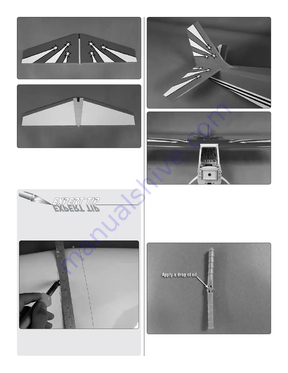
3. Remove the fin and stabilizer from the fuselage. Cut the 

covering from the stabilizer just inside of the lines you have 
drawn

. Be careful to only cut through the covering. 

DO 

NOT

 cut the wood structure. 

You may find it easiest to cut 

the covering away using the Expert Tip “How to Cut Covering 
from Balsa”.

HOW TO CUT COVERING FROM BALSA

Use a soldering iron to cut the covering from the stab. The 
tip of the soldering iron doesn’t have to be sharp, but a fi ne 
tip does work best. Allow the iron to heat fully.

Use a straightedge to guide the soldering iron at a rate that 
will just melt the covering and not burn into the wood. The 
hotter the soldering iron, the faster it must travel to melt a 
fi ne cut. Peel off the covering.

❏ 

4. Install the wing on top of the fuselage securing it with 

two 1/4-20 x 2" [51mm] nylon wing bolts. Glue the horizontal 
stabilizer and vertical fin in place on the fuselage with 30 
minute epoxy. Any excess glue can be cleaned up with paper 
towels and rubbing alcohol. Before the glue hardens check 
the alignment of the stab in relation to the wing to be sure 
they are aligned with each other. After you are satisfied things 
are aligned, leave the parts undisturbed until the glue has 
hardened. 

❏ 

5. Locate six hinges. Apply a drop of oil to each hinge to 

prevent glue from getting into the hinge when installing them 
in the stabilizer.

Содержание Citabria

Страница 1: ...photocopy of the purchase receipt Upon receipt of the package the problem will be evaluated as quickly as possible 2014 Great Planes Model Mfg A subsidiary of Hobbico Inc Wingspan 85 in 2160mm Weight 14 5 16 5 lb 6570 7480 g Motor Great Planes RimFire 1 60 63 62 250 Outrunner Brushless Length 62 in 1575mm Wing Area 1168 in2 75 3 dm2 Wing Loading 29 33 oz ft2 88 101 g dm2 SPECIFICATIONS INSTRUCTION...

Страница 2: ...Giant Scale Citabria ARF visit the Great Planes web site at www greatplanes com Open the Airplanes link then select the Giant Scale Citabria ARF If there is new technical information or changes to this model a tech notice box will appear in the upper left corner of the page AMA If you are not already a member of the AMA please join The AMA is the governing body of model aviation and membership pro...

Страница 3: ...he high stress points and or substituting hardware more suitable for the increased stress 7 WARNING The cowl and other miscellaneous parts included in this kit are made of fiberglass the fibers of which may cause eye skin and respiratory tract irritation Never blow into a part to remove fiberglass dust as the dust will blow back into your eyes Always wear safety goggles a particle mask and rubber ...

Страница 4: ...mber threads per inch and a length For example 4 40 3 4 19mm This is a number four screw that is 3 4 19mm long with forty threads per inch Socket Head Cap Screws SHCS are designated by a number threads per inch and a length For example 4 40 3 4 19mm This is a 4 40 SHCS that is 3 4 19mm long with forty threads per inch When you see the term test fit in the instructions it means that you should firs...

Страница 5: ...ow the instructions provided to locate a U S Canadian or International dealer Parts may also be ordered directly from Hobby Services by calling 217 398 0007 or via facsimile at 217 398 7721 but full retail prices and shipping and handling charges will apply Illinois and Nevada residents will also be charged sales tax If ordering via fax include a Visa or MasterCard number and expiration date for p...

Страница 6: ...r aileron servo Secure it with heat shrink tubing tape or other method for securing them together 2 Install a 8 200mm servo extension to your flap servo Secure it with heat shrink tubing tape or other method for securing them together 3 Remove the tape holding the servo covers to the bottom of the wing Locate two 5 16 x 3 4 x 3 4 8mm x 19mm x 19mm hardwood blocks Place your servo on the cover cent...

Страница 7: ...ll only through the plywood plate Do not drill through the top of the control surface Mount the horn with four 4 x 3 8 10mm screws 11 Each aileron and flap pushrod are made from a 5 3 4 146mm 4 40 pushrod wire threaded on one end a threaded metal clevis a 4 40 nut a metal solder clevis and two silicone clevis keepers 12 Screw the 4 40 nut and the threaded metal clevis onto the pushrod wire Attach ...

Страница 8: ...ldering This is what a properly soldered clevis looks like shiny solder with good flow no blobs and flux removed 13 Once the solder has cooled slide a silicone clevis keeper over each clevis Install the pushrod wire assembly to the aileron servo arm and aileron control horn 14 The flap control horn needs to be modified Trim a control horn as shown A high speed motor tool works well for this 15 Ins...

Страница 9: ...right wing 20 Once the glue has hardened test fit the two wing halves together by inserting the wing tube into one of the wings and then sliding the other wing onto the tube Once you are satisfied they fit together well set the wing aside and move on to the fuselage assembly ASSEMBLE THE FUSELAGE 1 Remove the windshield from the front of the fuselage It is attached to the fuselage with magnets Pul...

Страница 10: ...ews 6 lock washers and 6 flat washers Apply a drop of thread locker to each of the screws NOTE The landing gear will have a slight forward sweep when installed correctly Install the Stabilizer and Rudder 1 Locate the stabilizer and vertical fin Test fit them in place on the back of the fuselage 2 Use a felt tip pen to outline the fin on the top of the stabilizer and to outline the fuselage on the ...

Страница 11: ...ll just melt the covering and not burn into the wood The hotter the soldering iron the faster it must travel to melt a fine cut Peel off the covering 4 Install the wing on top of the fuselage securing it with two 1 4 20 x 2 51mm nylon wing bolts Glue the horizontal stabilizer and vertical fin in place on the fuselage with 30 minute epoxy Any excess glue can be cleaned up with paper towels and rubb...

Страница 12: ...all the rudder to the fin Install the Elevator and Rudder Servos 1 Install a 4 40 nut clevis keeper and 4 40 threaded clevis onto two 4 40 x 48 1220mm threaded wires 2 On the bottom of each elevator there is a plywood plate Install one of the clevises into the second hole from the bottom of a control horn Slide the 4 40 wire into the hole in the side of the fuselage and the place the control horn ...

Страница 13: ... secure the servos with the screws 7 Center the elevator halves and the two elevator servo arms Using the solder clevis as your guide make a mark on the pushrod wire where it needs to be cut Remove the clevis from the elevator control horn and remove the pushrod from the fuselage Do this for both pushrod wires Once the wires have been removed cut the wires on the marks you made Solder a 4 40 solde...

Страница 14: ...Apply a drop of thin CA glue to harden the threads When the glue has hardened secure the servo with the screws 13 Center the rudder and the rudder servo arm Using the solder clevis as your guide make a mark on the pushrod wire where it needs to be cut Remove the clevis from the rudder control horn and remove the pushrod from the fuselage Cut the wire on the mark you made Solder a 4 40 solder clevi...

Страница 15: ...ass couplers two 2 56 nuts two silicone clevis keepers and two copper crimp connectors Slide a crimp connector onto one end of the braided cable Insert the braided cable into the hole in the end of one of the 2 56 brass couplers and loop it back through the crimp connector Crimp the connector tightly with a pliers to secure the connector to the braided cable Install a 2 56 nut clevis keeper and 2 ...

Страница 16: ... the covering to reveal the vents 2 To install the motor you will need a motor mount We recommend the Great Planes large engine mount GMPG1260 This mount is strong lightweight and allows for infinite adjustment to accommodate most motor brands 3 On page 43 of the instruction manual is a paper template for the Great Planes large engine mount Cut the pattern from the manual Tape the pattern to the f...

Страница 17: ... x 3 8 10mm screws and 4 flat washers 9 Just behind the landing gear is a hardwood stick that will be used for securing your ESC tray Slide the tray to the front of the firewall Insert the two tabs into the slots in the firewall to retain the front of the tray and let the back of the tray rest on the hardwood stick Drill a 1 16 1 6mm hole through the mounting holes in the tray into the hardwood st...

Страница 18: ...batteries The straps can be inserted through the slots in the tray 13 We have included a secondary battery tray Depending on your choice of motor and batteries your airplane could be slightly nose heavy If this is the case install the secondary battery tray as shown It can be secured by drilling a 3 32 2 5mm hole through each of the mounting holes and into the plywood rails on each side of the fus...

Страница 19: ... you will need to remove a small amount of the bottom of the firewall 2 Install engine mounting bolts flat washers and lock washers from the back of the firewall The mounting hardware is not included in this kit It should come with the engine If your engine did not include fender washers purchase four fender washers to mount the bolts from behind the firewall The fender washer helps to better spre...

Страница 20: ... 6 4mm hole on the mark for the fuel line Check the diameter of your fuel line to be sure that a 1 4 6 4mm hole is correct 8 Assemble the fuel tank stopper assembly with the fuel tubes as shown The easiest way is to first solder a fuel line barb not included onto one end of all three tubes We used the 1 8 Dubro Fuel Line Barbs DUBQ0670 Insert the tubes into the stopper with the metal plates and th...

Страница 21: ... the tank in the fuselage 12 Install the throttle and choke optional servos as shown The servos can be mounted on both sides of the fuselage if your carburetor happens to be on the opposite side of the engine than our DLE 30 Install the servos with the hardware provided with your servos 13 Locate one of the nylon ball links Cut it in half as shown 14 Locate the 11 3 4 plastic pushrod tube Cut a 4 ...

Страница 22: ...Snap the nylon ball link onto the ball link on the choke servo 17 Move the choke arm towards the firewall Position the servo arm as shown Bend the pushrod wire in line with the outer hole in the servo arm Drill the outer hole in the servo arm with a 5 64 2mm drill 18 Locate the plywood pushrod support and the two 1 4 x 1 4 x 1 2 6 x 6 x12mm hardwood sticks ...

Страница 23: ...ion of the plastic pushrod tube you cut in step 15 Roughen the end of the tube with 120 grit sandpaper Use 5 minute epoxy and glue the tube into the hole you drilled for the throttle linkage 23 Drill the outer hole in the throttle servo arm with a 5 64 2mm drill 24 Thread a nylon ball link onto a 2 56 x 6 pushrod wire Insert the wire into the plastic tube through the firewall Snap the nylon ball l...

Страница 24: ...the hardwood stick Secure the tray to the stick with three 2 x 3 8 10mm screws and 2 flat washers The spark plug lead and ignition module connection should feed through the opening in the firewall Screw the plywood plate in place with four 2 x 3 8 9mm screws and 2 flat washers as shown in the photo 29 The installation shown of the DLE 30 assumes the installation of the stock muffler but if you cho...

Страница 25: ...with one another The easiest way to do this is to slide disk 1 onto the front of the engine Then glue disk 2 to disk 1 again sliding disk 2 onto the engine When the glue has hardened slide disk 3 onto the crankshaft and glue it to disk 2 This assembly does not require much glue for where it will be used A small amount of medium CA glue should work well Once the glue has hardened remove it from the...

Страница 26: ...loons to thicken the glue Use a long stick or rod and apply a small amount of epoxy to the cowl ring and the cowl Apply the glue in four to six spots to tack glue the cowl to the cowl ring Allow the glue to harden 7 Remove the disk assembly from the front of the cowl Use a long handled ball wrench and remove the bolts holding the cowl in place Remove the cowl being careful not to break the cowl ri...

Страница 27: ...hown here Screw it in place as shown This will allow the spark plug lead and the ignition lead to be routed clear of the muffler 11 Install the muffler of your choice 12 Slide the cowl onto the front of the fuselage Work slowly and mark where the cowl needs to be cut to allow it to fit completely over the engine Continue until the cowl will slip over the engine and can be bolted to the firewall 13...

Страница 28: ...t a 6 32 set screw into two of the 3 16 4 8mm wheel collars Slide one wheel collar onto the axle followed by the wheel and then another 3 16 4 8mm wheel collar Center the wheel and then tighten the set screws Be sure the wheel collar on the end of the axle rests on the flat spot you made 4 Slide the wheel pant over the wheel and axle Secure the pant to the landing gear with two 4 40 x 1 2 13mm soc...

Страница 29: ... flat washers Be sure to apply a drop of thread locker on each of the screws before inserting them into the brackets 7 Your kit includes 2 pair of struts Each pair is comprised of a 24 610mm and 25 1 2 647mm long strut The 24 610mm strut is the front strut and the 25 1 2 647mm strut is the rear strut 8 There are two different brackets used for mounting the strut You will need two of the 90 degree ...

Страница 30: ...hown 13 Install the wing struts to the wing and the fuselage with a 4 40 x 1 2 13mm socket head cap screw 4 flat washer and 4 lock washer mounting it to the bracket extending from the fuselage and the two blind nuts located in the wing near the wing tip Attach the struts to the fuselage with a 4 40 x 1 2 13mm socket head cap screw 4 flat washer and 4 lock washer 14 Locate the two interplane struts...

Страница 31: ...selage Remove the wing bolts and then slide the wing out of the wing saddle continuing back towards the tail Once the wing is far enough aft of the wing saddle the struts will be wider than the fuselage At that point you can lift the wing off the fuselage Using this method for installing and removing the wing you can leave the struts on the wing halves This makes installation of the wings and stru...

Страница 32: ...ervo lead or Y harness on the flap leads and the aileron leads in your wing INSTALL THE COCKPIT PILOT AND SPINNER 1 Locate the cockpit floor and the seat backs Glue the seat backs to the cockpit floor 2 Remove the windshield and un do the Velcro holding the fuel tank in place Test fit the cockpit floor inside the fuselage The cockpit floor is pre cut and should fit without any modifications The ea...

Страница 33: ...ece of self adhesive Velcro to the inside of the cover 6 Attach a 1 25mm piece of self adhesive Velcro to the back of the fuel tank This will secure the cover and allow it to be easily removed if you need to service the fuel tank 7 Now is a good time to decide if you will install a pilot We used the Great Planes 1 4 scale sport pilot figure GPMQ9010 Because the cockpit floor is vacuum formed plast...

Страница 34: ... fuselage 8 If you choose not to install a pilot secure the floor to the rails in the fuselage by drilling four 1 16 1 6mm holes through the floor and the mounting rails Secure the floor with four 2 x 3 8 10mm screws and 2 flat washers Refer to the above photo to see the location of the screws we installed 9 Apply the instrument panel decal to the instrument panel shroud 10 Install the instrument ...

Страница 35: ...e lower corner of the screen as shown in the photo This will allow you the access you need Once you have modified the screen or cowl as needed glue the screen inside the cowl 12 Install the spinner onto the front of the engine or motor The spinner back plate is pre drilled for the O S GT33 The spinner also comes with a bushing that will allow the back plate to be used on smaller shafts that may be...

Страница 36: ...all the screws that hold on the servo arms 2 With the transmitter and receiver still on check all the control surfaces to see if they are centered If necessary adjust the clevises on the pushrods to center the control surfaces FULL THROTTLE RUDDER MOVES RIGHT ELEVATOR MOVES DOWN RIGHT AILERON MOVES UP LEFT AILERON MOVES DOWN 4 CHANNEL RADIO SET UP STANDARD MODE 2 3 Make certain that the control su...

Страница 37: ...r the C G center of gravity balance point can have the greatest effect on how a model flies and could determine whether or not your first flight will be successful If you value your model and wish to enjoy it for many flights DO NOT OVERLOOK THIS IMPORTANT PROCEDURE A model that is not properly balanced may be unstable and possibly unflyable At this stage the model should be in ready to fly condit...

Страница 38: ...and place it on or inside your model Charge the Batteries Follow the battery charging instructions that came with your radio control system to charge the batteries You should always charge your transmitter and receiver batteries the night before you go flying and at other times as recommended by the radio manufacturer CAUTION Unless the instructions that came with your radio system state different...

Страница 39: ...ber on or in the model Note This does not apply to models while being flown indoors 7 I will not operate models with pyrotechnics any device that explodes burns or propels a projectile of any kind Radio Control 1 I will have completed a successful radio equipment ground check before the first flight of a new or repaired model 2 I will not fly my model aircraft in the presence of spectators until I...

Страница 40: ...larming or unusual sound such as a low pitched buzz this may indicate control surface flutter Flutter occurs when a control surface such as an aileron or elevator or a flying surface such as a wing or stab rapidly vibrates up and down thus causing the noise In extreme cases if not detected immediately flutter can actually cause the control surface to detach or the flying surface to fail thus causi...

Страница 41: ...llooning is eliminated We recommend you spend some time flying with the flaps deployed flying at slower speeds Landing To initiate a landing approach lower the throttle while on the downwind leg Allow the nose of the model to pitch downward to gradually bleed off altitude Continue to lose altitude but maintain airspeed by keeping the nose down as you turn onto the crosswind leg In the crosswind le...

Страница 42: ...42 This model belongs to Name Address City State Zip Phone Number AMA Number ...

Страница 43: ... This pattern is oriented for an inverted engine installation Examine the mounting holes on the engine and be sure you orient the drilling pattern for the orientation of your engine GREAT PLANES BRUSHLESS LARGE MOTOR MOUNT RIMFIRE 1 60 47mm 47mm ...

Страница 44: ......

Отзывы: