background image

GRAUPNER GmbH & Co. KG D-73230 KIRCHHEIM/TECK GERMANY


No liability for printing errors. Technical modifications reserved! 


03/2011


8


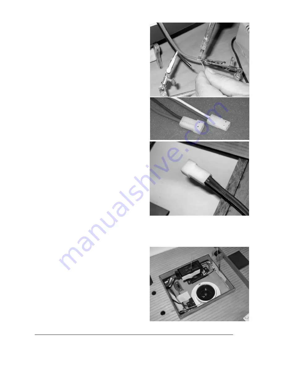
Solder a G2 connector to the motor wires, referring to 
the wiring diagram on page 13 (+ is red, - is black). 
Check the direction of operation of the motor: when 
the battery is connected, the motor shaft must rotate 
in such a way that the boat will be propelled forward. 

NOTE: 

the polarity of the G2 connector system is 

designed in such a way that the raised lug on the 
plastic housing is always the positive terminal (red 
wire). If you keep consistently to this arrangement, 
your drive batteries and speed controllers will always 
be compatible with each other, and reversed polarity 
problems will not arise. We recommend following one 
of the tips below in order to make it easier to solder 
the joints; this reduces the likelihood of damaging 
detail features on the model with the hot soldering 
iron. 

TIP 1:

 remove the motor: undo the grubscrews 

in the propeller, then withdraw the propeller. Loosen 
the motor retaining screws (accessible through the 
two holes in the deck - don’t remove the screws 
completely! - and then withdraw the motor to the 
point where the shaft coupling is exposed. Loosen 
the grubscrews in the coupling which clamp the motor 

shaft, and then remove the motor from the model. 
Reverse the sequence to re-install it. 

TIP 2:

 if you 

have a friend to help you, ask him or her to hold the 
boat at an angle, so that you can hold the wires 
outside the hull for soldering the connector. 

TIP 3:

 it 

is possible to solder the joints directly inside the 
model (see photo) if you have access to the tool 
known as a “third hand”. 

  Check that the screws in the shaft coupling, the 

motor retaining bar and the propeller are tight, as 
they may have worked loose in transit. You can 
check this by pulling on the propeller: if there is axial 
play in the shaft, then one of the grubscrews is loose. 
Tighten any loose grubscrews cautiously, following 

TIP 1

 above to gain access to them. 

IMPORTANT:


we recommend that you apply a drop of thread-lock 
fluid, e.g. UHU schraubensicher (Order No. 952) to each grubscrew, as vibration when the boat is 
operating may cause them to work loose again. 


Connect the speed controller wires to those attached to the motor, and fix the controller to the inside of the 
hull using Velcro (hook-and-loop) tape. 


Connect the two battery connectors to the distributor lead (Order No. 3068). 


Attach the receiver to the inside of the coaming under 
the bridge superstructure. Stick the aerials of the 
HoTT receiver in place, with the final 30 mm of the 
aerial wires pointing upward; this will ensure optimum 
reception. If you are using a conventional 40 MHz 
receiver, the wire aerial must be deployed under the 
deck, and taped in place. 

IMPORTANT: 

it is essential 

to locate the aerial or aerials above the waterline, 
otherwise radio reception will not be possible. 

Содержание WEGA

Страница 1: ...rer s declaration from Graupner GmbH Co KG Content of the manufacturer s declaration If material defects or manufacturing faults should arise in a product distributed by us in the Federal Republic of Germany and purchased by a consumer 13 BGB we Graupner GmbH Co KG D 73230 Kirchheim Teck Germany acknowledge the obligation to correct those defects within the limitations described below The consumer...

Страница 2: ...ay Unless otherwise prescribed by binding law the obligation of the GRAUPNER company to pay compensation regardless of the legal argument employed is excluded This includes personal injury death damage to buildings loss of trade or turnover interruption of business or other indirect or direct damages which are caused by the operation of the model Under all circumstances and in all cases the compan...

Страница 3: ... speed controller and or the rudder servo may be ruined due to overloading Before running the model check that the sheets are free moving and have not become tangled or caught up on the model Dry cells and rechargeable batteries must never be short circuited Do not allow them to come into direct contact with water Remove the drive battery and any dry cells from the boat and the transmitter before ...

Страница 4: ...GRAUPNER GmbH Co KG D 73230 KIRCHHEIM TECK GERMANY No liability for printing errors Technical modifications reserved 03 2011 4 Terms ...

Страница 5: ...contact from the connector housing Bend the wire double and wrap adhesive tape round the bare contact to insulate it NOTE this measure is necessary because both the sailwinch and the speed controller feature a BEC system and only one of them may be used If you are installing the recommended RC components the NAVY V40R features the more powerful BEC system so this one should be used Unscrew the she...

Страница 6: ...ORTANT apply a drop of cyano acrylate to the knot to secure it IMPORTANT ensure that the upper sheets are wound onto the upper reel When you are satisfied screw the sheet guide flange in place again IMPORTANT check that the sheets are not tangled or twisted before you secure the flange Wind a short length of the sheets onto the winding reel then fit the winding reel on the sailwinch and tighten th...

Страница 7: ...e brass spacer sleeves through the grommets from the underside Place the rudder servo in the appropriate aperture and fit the retaining screws Use a 2 mm Ø bit to drill out the centre hole in the double sided servo output lever Fit the angled end of the pre formed pushrod in the hole and secure it with the retaining clip The prepared output lever can now be screwed to the servo after setting it to...

Страница 8: ... install it TIP 2 if you have a friend to help you ask him or her to hold the boat at an angle so that you can hold the wires outside the hull for soldering the connector TIP 3 it is possible to solder the joints directly inside the model see photo if you have access to the tool known as a third hand Check that the screws in the shaft coupling the motor retaining bar and the propeller are tight as...

Страница 9: ...The final trim is carried out later when the boat is complete by installing additional ballast Attach the bowsprit to the model withdraw the retaining pin from the bracket on the deck slide the bowsprit through the opening and into the hull before re fitting the pin to secure it Connect the bowsprit rigging to the rings already attached to the model The next step is to prepare the schooner mast an...

Страница 10: ...h the square sail bunt lines and sheets Set the sailwinch to minimum travel then run the sailwinch to the end point at which the sails are fully close hauled Tie the sheets to the booms but use knots which can be loosened again later Slacken the sails until the winch is at the other end of its travel If the linear movement is insufficient increase the travel at the winch CAUTION since the winch tr...

Страница 11: ...30 KIRCHHEIM TECK GERMANY No liability for printing errors Technical modifications reserved 03 2011 11 Glue the radar apparatus in the intended position and insert the three pins Glue the four davits in the openings in the deck ...

Страница 12: ...as tacking and involves sailing in a zig zag pattern for a while on the port tack mainsail on the left hand port side of the boat 2a then after going about the boat s bow turns through the wind from position 2a via 1 to 2b for a while on the starboard tack mainsail on the right hand starboard side of the boat 2b etc Fast efficient tacking with a sailing boat demands a good eye and considerable man...

Страница 13: ...llably into the wind if the breeze is too powerful This means that the sail area is too great if there is no alternative smaller sail suit available sailing is not possible in these conditions Wiring diagram Maiden run Wait for a day with optimum wind conditions and seek out a stretch of water where you can easily salvage the boat if necessary Charge up the batteries and check the model s working ...

Отзывы: