10
angled tubes must be positioned at the bottom of the tank (this is the filler line), and the other should point
up to act as overflow when refueling. This tube will later be connected to the silencer pressure nipple. Cut
three length of silicone fuel tubing and push them onto the tubes where they exit the fuel stopper. Mark
the fuel lines using a felt-tip pen to indicate which is the fuel feed, the overflow and the filler. Fit the tank
sealing ring over the neck of the fueltank and tighten the cross-point screw to clamp it in place. Be sure to
tighten the screw to the point where there is no chance of the tank leaking.
Fit the fueltank into the tank compartment in the fuselage through the wing saddle, threading the three
silicone fuel tubes through the hole in the nose bulkhead. Pack foam rubber round the tank to cut down
vibration and to prevent it shifting in flight.
Connecting the fuel lines
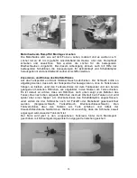
Locate the silicone fuel line attached to the fueltank clunk pick-up (fuel feed) and connect it to the
carburettor inlet nipple. Connect the overflow line to the pressure nipple on the silencer.
We recommend that you route the filler line out of a hole in the cowl, and seal it with a sealing nipple,
Order No. 140, before flight.
When you are filling the fueltank watch the overflow carefully; it is important that you don’t flood the
silencer with excess fuel at this point.
The cowl can now be fitted to the fuselage, and the propeller and spinner mounted on the motor. It is
important to check regularly that the propeller is firmly seated on the motor’s crankshaft.
Assembling the TAXI CUP II
To connect the aileron servo to the receiver we recommend using a suppressor filter, Order No. 1040,
connected to the appropriate receiver output (2).
Wrap the receiver battery in foam and push it into the space under the fueltank inside the fuselage. Make
sure that the receiver battery cannot possibly shift while the model is in flight. Connect the aileron servo to
the extension lead and fit the wing on the fuselage; secure it by tightening the four retaining screws.
Balancing the TAXI CUP II
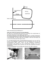
Support the model under both wing roots at a point about 90 mm aft of the wing leading edge. If the CG
position is correct the model will hang level, with the nose inclined slightly down.
If necessary glue lead ballast to the nose or tail to obtain the correct balance.
An alternative method of balancing is to re-position the receiver battery further forward or aft. All the
control surfaces must be exactly at centre when the transmitter trims and sticks are in the neutral position.
Check this before the first flight.
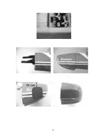
Control surface travels
Ailerons
10 mm up and down
)
Elevators
11 mm up and down
)
30% exponential
Rudder
35 mm right and left
)
The stated control surface travels are only recommended values. You may wish to adjust them later to
suit your personal preference.
Important:
When fitting and adjusting the various linkages you should ensure that they move freely, without binding,
are able to move to their full extent - including trim travel - and are not obstructed mechanically at any
point.
When you move the rudder stick to the right, the rudder should also deflect to the right (left stick: left
rudder). Pull the elevator stick back towards you, and the elevators must both deflect up (stick forward:
both elevators down). If you move the aileron stick to the right, the right-hand aileron should rise, the left-
hand aileron fall. When you move the throttle stick forward, the motor should run to the full-throttle
position, i.e. the carburettor barrel should be fully open.
Finally - we hope you have many hours of fun and pleasure flying your TAXI CUP II.
GRAUPNER GmbH & Co. KG D-73230 KIRCHHEIM/TECK GERMANY
We reserve the right to introduce modifications. No liability for printing errors. 02/2004
Made in Vietnam
Содержание TAXI CUP II
Страница 21: ...21 ...

