


8
The final job involving the wing is to open up the four holes for the wing retainer screws on the top and
bottom surface of the wing roots. Locate the holes with your finger, then carefully melt away the covering
film using a soldering iron.
Gluing the tailplane and fin to the fuselage
Use a soldering iron to remove the covering film over the slots for the fin and tailplane in the tail end of
the fuselage. This is done by locating the slots with your fingertips, pushing the tip of the soldering iron
through and running it along the edge of the slots until all the film has been melted away. Please note that
the soldering iron should be of relatively low wattage; there should be just sufficient heat to melt the film.
Repeat the procedure with the slots for the rudder and elevator linkages.
Note: there are two elevator pushrods - one each side!
Slide the tailplane and fin into their slots. Adjust the position of the tailplane until it projects by exactly the
same length on both sides, and is at right-angles to the fuselage centreline when viewed from above.
Mark the outside shape of the fuselage on the tail panels using a felt-tip pen.
Melt the covering film along the marked lines by running a soldering iron lightly along a ruler or setsquare.
Keep slightly inside the lines, and carefully peel the film away from the wood.
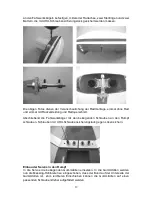
Fit the tail panels in the fuselage slots again, align them carefully and glue them in place. UHU coll (white
glue) can be used for this, but UHU plus endfest 300 (slow-setting epoxy) is better. Align the parts as
described at the start of this section: the fin must be at right-angles to the tailplane. This can be checked
with a setsquare or an engineer’s square as shown in the photo. Pin the parts in place while the glue is
hardening.
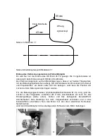
Carry out the measurements as shown in the photos to ensure that the wing and tailplane are properly
“square” to the fuselage centreline. The measured values must be the same on both sides of the model.
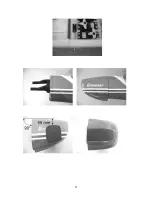
Installing the rudder and elevator horns
The horns must be mounted on the rudder and elevators in such a way that the clevis linkage points are
exactly in line with the hinge axis. Drill holes in the control surfaces for the horn retaining screws. The
clevises can now be fitted on the pushrods, as described for the aileron linkage, and connected to the
second hole from the outside of the horns.
Screw the horns in place, and file back the excess screw material flush with the spreader plates.
Take care that the elevator horn does not foul the rudder horn on that side; you may have to shorten the
elevator horn by one hole to provide clearance.
Installing the tailwheel unit
Fix the tailwheel unit to the fuselage using two pan-head self-tapping screws as shown in the photo.
Important: the hinge axis of the rudder must coincide with the pivot axis of the tailwheel leg. Fit the U-
shaped plastic part on the driver pin (steel rod) and fix it to the rudder using a pan-head self-tapping
screw; remember to drill a pilot-hole in the rudder beforehand. Cut off the excess steel rod.
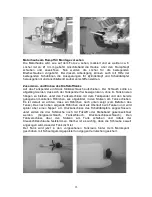
Installing the main undercarriage
The first step here is to drill holes in the wheel spats for the wheel axles. Extend the holes on the inside of
each wheel spat (facing the undercarriage units) to form slots, as this makes it easier to assemble the
parts. The wheels can now be attached to the undercarriage units using one wheel axle, two collets and
two nuts each. Remember to secure all the screwed joints with UHU thread-lock fluid.
The four photos here are intended to clarify how the wheels are mounted; they show the installation once
without the wheel, once with the wheel spat, and once with a cross-section of the wheel.
Attach the main undercarriage unit to the underside of the fuselage using the screws provided. Secure
the screws with a drop of UHU thread-lock fluid to prevent them shaking loose.
Installing the servos in the fuselage
Press the rubber grommets (supplied with the servos) into the servo mounting lugs. Push the brass
tubular rivets into the rubber grommets from the underside, so that the flange is at the bottom. You may
find it easier to insert the tubular rivets if you fit them on a small screwdriver first.
Содержание TAXI CUP II
Страница 21: ...21 ...


