Starlet 50
27
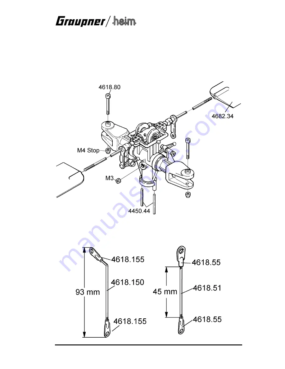
Roughen the surface of the flybar at the point where the control bridge 4618.37 is to be
clamped. Screw the control bridge to the flybar, applying thread-lock fluid between the bar and
the control frame to prevent any danger of the flybar rotating in the control bridge during violent
aerobatic manoeuvres.
Slip the ball-collets 4607.36 on both ends of the flybar, and position them resting against the
control bridge. Before fitting the M3 x 3 grubscrews apply a drop of thread-lock fluid to the
threaded holes in the ball-collets. Press the double ball-links 4607.35 into place as shown.
Apply thread-lock fluid to the sockets in the flybar paddles 4682.34, and screw them onto the
ends of the flybar to a depth of exactly 15 mm. Set them exactly parallel to each other and to the
control bridge.
Press an M3 nut into the recess in one side of the rotor head hub, and press the two guide pins
4450.44 for the collective pitch compensator into the holes, applying thread-lock fluid to the
sockets first.
Make up two straight and two angled pushrods as shown in the drawing.


