background image

July 3, 2007

K2 Storage System Instruction Manual

211

Configuring RAID

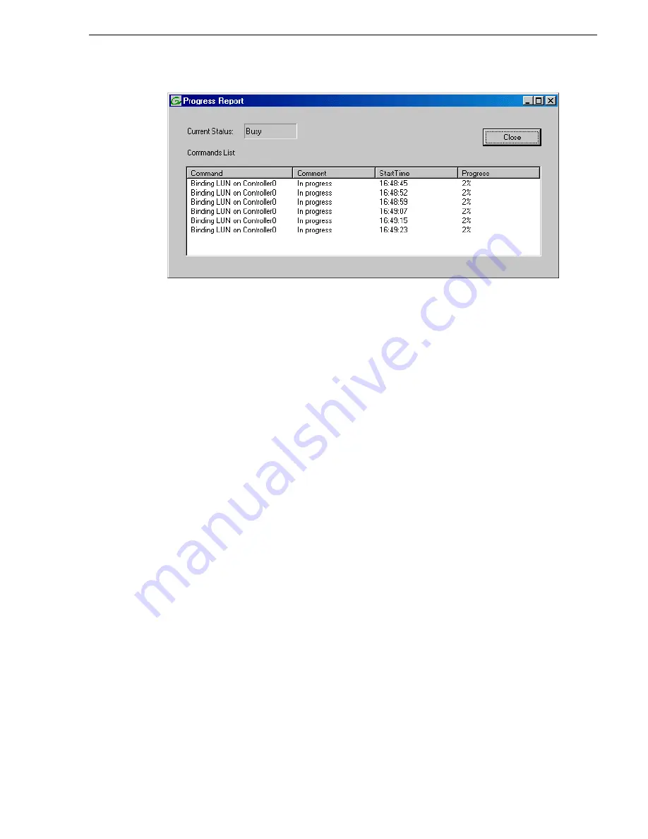
f. Close the Progress Report and repeat these steps for other unbound disks. If 

specified by your system design, you can bind some disks as Hot Spares, as 
explained in 

“Binding Hot Spare drives” on page 381

. When you are done, if 

you did not bind any extra Hot Spares, you should have the following results:

For Level three redundant storage, on the primary RAID chassis you should 
have two RAID 1 LUNs of two disks each, one Hot Spare Disk, and two RAID 
5 LUNs of five disks each. For each optional Expansion chassis, you would have 
an additional three RAID 5 LUNs of five disks each. If using RAID 6, LUNs are 
six disks each.

NOTE: Controllers can take several hours to bind a LUN. Make sure you initiate 
multiple simultaneous binding processes to reduce the overall time.

g. Upon 100% completion, click 

Close

 in Progress Report window.

NOTE: Do not proceed until all LUNs are finished binding.

4. Restart the K2 Media Server.

NOTE: Make sure start up processes on the K2 Media Server are complete before 
proceeding. 

5. Continue with the next procedure 

“Creating a new file system”

.

Содержание K2 BASECAMP EXPRESS

Страница 1: ...K2 STORAGE SYSTEM Instruction Manual SOFTWARE VERSION 3 2 071 8461 02 JULY 2007 ...

Страница 2: ...dditional information regarding Grass Valley Inc trademarks and other proprietary rights may be found at www thomsongrassvalley com Disclaimer Product options and specifications subject to change without notice The information in this manual is furnished for informational use only is subject to change without notice and should not be construed as a commitment by Grass Valley Inc Grass Valley Inc a...

Страница 3: ...ning a new K2 Storage System 50 Configuring the server Part 1 52 Configuring RAID 54 Creating a new file system 59 Configuring the server Part 2 60 Adding K2 Storage System clients 63 Basic operations for Level 2 storage 63 Level 2 system power off procedure 63 Level 2 system power on procedure 65 67 Chapter 3 Installing the Level 2R Storage System Level 2R system description 70 Preparing Level 2R...

Страница 4: ...51 Prerequisites for initial configuration 151 Defining a new K2 Storage System 152 Configuring the server Part 1 154 Configuring RAID 156 Creating a new file system 161 Configuring the server Part 2 162 Configuring server 2 165 Adding K2 Storage System clients 168 Basic operations for Level 3 storage 168 Level 3 system power off procedure 168 Level 3 system power on procedure 170 172 Chapter 5 In...

Страница 5: ...st tables 257 Testing the control network 258 Configuring the nearline storage system 260 Prerequisites for initial configuration 260 Defining a new K2 Storage System 261 Configuring the server Part 1 263 Configuring RAID 265 Creating a new file system 272 Configuring the server Part 2 273 Configuring remaining servers 275 Basic operations for nearline storage 278 Nearline system power off procedu...

Страница 6: ... Accessing K2 Storage System features 325 Renaming a K2 Storage System 325 Adding devices to a K2 Storage System 326 Removing a K2 Storage System 327 Accessing a K2 Storage System from multiple PCs 328 Reconnecting to a K2 Storage System 329 Taking a K2 Storage System offline 329 Bringing a K2 Storage System online 329 Managing redundancy on a K2 Storage System 330 Identifying current primary back...

Страница 7: ...xpanding the media file system by capacity 354 Expanding the media file system by bandwidth 355 Backing up the media database 359 Working with RAID storage 376 Checking RAID storage subsystem status 376 Checking controller microcode 377 Identifying disks 377 Get controller logs 378 Unbind LUN 378 Binding LUNs 379 Binding Hot Spare drives 381 Loading RAID controller microcode 382 Downloading disk d...

Страница 8: ...8 K2 Storage System Instruction Manual July 3 2007 Contents ...

Страница 9: ... be connected to earth ground Before making connections to the input or output terminals of the product ensure that the product is properly grounded Do Not Operate Without Covers To avoid electric shock or fire hazard do not operate this product with covers or panels removed Do Not operate in Wet Damp Conditions To avoid electric shock do not operate this product in wet or damp conditions Do Not O...

Страница 10: ...can result in personal injury or loss of life CAUTION Caution statements identify conditions or practices that may result in damage to equipment or other property or which may cause equipment crucial to your business environment to become temporarily non operational Terms on the Product These terms may appear on the product DANGER indicates a personal injury hazard immediately accessible as one re...

Страница 11: ...ections Certifications and Compliances Canadian Certified Power Cords Canadian approval includes the products and power cords appropriate for use in the North America power network All other power cords supplied are approved for the country of use FCC Emission Control This equipment has been tested and found to comply with the limits for a Class A digital device pursuant to Part 15 of the FCC Rule...

Страница 12: ...ceived including interference that may cause undesirable operation Laser Compliance Laser Safety Requirements The device used in this product is a Class 1 certified laser product Operating this product outside specifications or altering its original design may result in hazardous radiation exposure and may be considered an act of modifying or new manufacturing of a laser product under U S regulati...

Страница 13: ...for compliance with ANSI UL60950 CAN CSA C22 2 No 60950 00 12 01 2000 Safety of Information Technology Equipment including Electrical Business Equipment Third edition IEC 950 Safety of Information Technology Equipment including Electrical Business Equipment Third edition 1999 EN60950 Safety of Information Technology Equipment including Electrical Business Equipment Third Edition 2000 ...

Страница 14: ...14 K2 Storage System Instruction Manual July 3 2007 Safety Summaries ...

Страница 15: ...escribes the chapters included in this manual Chapter 1 Product Description Provides the product functional description and an overview of the key features Chapter 2 to Chapter 6 These chapters provide procedures for installing configuring and operating the different levels of the K2 Storage System as follows Chapter 2 Installing the Level 2 Storage System Chapter 3 Installing the Level 2R Storage...

Страница 16: ... a m i l y o f X P S e r i e s F a m i l y o f X P S e r i e s F a m i l y o f X P S e r i e s F a m i l y o f X P S e r i e s G r a s s V a l l e y G r o u p K2 Media Client Release Notes Path for the operator The latest information about the hardware and software shipped with the system F a m i l y o f X P S e r i e s F a m i l y o f X P S e r i e s F a m i l y o f X P S e r i e s F a m i l y o ...

Страница 17: ... the product specifications and step by step instructions for modifying system settings Includes instructions for adding a K2 Media Client to the K2 Storage System K2 Media Client Quick Start Guides The Quick Start Guides provides step by step installation instructions for basic installation and operation of the K2 Media Client including recording and playing clips K2 Media Client User Manual Desc...

Страница 18: ...Information referenced on the Dell Product Documentation CD ROM includes but is not limited to Unpacking and rack mounting the K2 Media Server Important safety and regulatory information K2 Media Server Status indicators messages and error codes Troubleshooting help for the K2 Media Server hardware CAUTION Do not use the Dell Quick Installation Guide provided with the Dell CD ROM package This guid...

Страница 19: ...oduct support by phone during business hours Afterhours phone support is available for warranty and contract customers Authorized Support Representative A local authorized support representative may be available in your country To locate the support representative for your country visit the product support Web page on the Grass Valley Web site International France 800 80 80 20 20 33 1 48 25 20 20 ...

Страница 20: ...20 K2 Storage System Instruction Manual July 3 2007 Finding Information ...

Страница 21: ...July 3 2007 K2 Storage System Instruction Manual 21 Chapter 1 Product Description This chapter describes the K2 Storage System as follows Overview Description on page 22 Key features on page 23 ...

Страница 22: ...sections later in this manual for the system description of each of the different levels of storage available as follows Level 2 system description on page 26 Level 2R system description on page 70 Level 3 system description on page 126 Level 3R system description on page 174 Refer to the K2 Media Client System Guide for diagrams and explanations of the media file system and the media database The...

Страница 23: ...5 and 6 storage FTP transfers Standard IT networked storage configurations to fit a wide variety of size and performance requirements Scaling from 100 to 1000MB s Redundancy and fault recovery with no single point of failure Tuned and optimized file system for reliable and robust transaction of media files Best in class storage management for high throughput deterministic performance with load bal...

Страница 24: ...24 K2 Storage System Instruction Manual July 3 2007 Chapter 1 Product Description ...

Страница 25: ... the following topics Level 2 system description on page 26 Preparing Level 2 devices on page 27 K2 configuration and NetCentral on page 44 Networking for Level 2 on page 45 Configuring the Level 2 storage system on page 49 Adding K2 Storage System clients on page 63 Basic operations for Level 2 storage on page 63 Work through these topics sequentially to install the storage system ...

Страница 26: ...SI interface cards provide a bridge between GigE iSCSI and Fibre Channel SCSI The server also hosts software components that allow it to function in various roles including media file system manager media database server and FTP server The L2 RAID chassis is connected via a single Fibre Channel connection to the K2 Media Server It is also connected to the GigE control network which is required for...

Страница 27: ...em Guide for rack mount instructions Use a PC that you own and install the required software For either option you must do the following for the Control Point PC that runs the K2 System Configuration application Assign a control network IP address to the PC Refer to Networking tips on page 56 Connect the PC to the GigE control network To use your own PC you must additionally do the following Verif...

Страница 28: ...itches on page 388 Use CAT5e or CAT6 cables The maximum cable length is 50 meters for CAT5e and 100 meters for CAT6 Assign an IP address and logon to the switch Refer to Configuring the GigE switch via serial connection on page 29 Set up VLANs on the switch Refer to Configuring the GigE switch via the Web interface on page 32 Install the switch in its permanent location Provide power to the switch...

Страница 29: ...et to Xon Xoff Also disable uncheck the Use Function Arrow and Ctrl Keys for Windows option 2 Connect the PC to the switch s Console Port using the console cable included with the switch If your PC or terminal has a 25 pin serial connector first attach a 9 pin to 25 pin straight through adapter at one end of the console cable 3 Turn on the PC s power and start the PC terminal program 4 Press Enter...

Страница 30: ...following then press Enter configure You are now in configuration mode 18 Configure an administrator username The username can be one that is used on other K2 devices such as administrator or K2admin or it can be your site s administrator username For example to set the username to administrator type the following then press Enter password manager user name administrator 19 When prompted enter and...

Страница 31: ...gn considerations for Ethernet switches on page 388 and consult with your Grass Valley representative if your requirements deviate from the recommended policy a At the main menu select Switch Configuration and press Enter b Choose selection Port Trunk Settings and press Enter c Press the right arrow key to choose Edit then press Enter d Down arrow until at the bottom of the list of ports e Right a...

Страница 32: ...You can now use the switch s web browser interface for further configuration as instructed in the next procedure 33 Close the PC terminal program and disconnect the console cable Continue with the next procedure Configuring the GigE switch via the Web interface Configuring the GigE switch via the Web interface The following procedure is for the HP ProCurve switch and applies to both the 3400cl ser...

Страница 33: ...assword 6 Click Port Configuration 7 If you do not need trunks such as on a one switch system skip to the next step in this procedure If you need trunks such as on a two switch system with ISLs do the following a Select Ctrl Click the trunked ports Typically the trunked ports are at the bottom of the list In the configuration for 10 Gig ISLs two of the ports at the bottom of the list are labeled T...

Страница 34: ...ol as follows For the 3400cl series switch set to Disable For the 2900 series switch set to Enable If you have both 3400cl series and 2900 series on your network having different Flow Control settings disable for 3400cl enable for 2900 does not cause problems e Click Apply Settings 8 On the Port Configuration page do one of the following If you do not have trunks select all ports If you have trunk...

Страница 35: ...r the 2900 series switch set to Enable If you have both 3400cl series and 2900 series on your network having different Flow Control settings disable for 3400cl enable for 2900 does not cause problems 12 Click Apply Settings Wait until settings are applied and the Web interface becomes active 13 Choose VLAN Configuration If prompted log in with the switch s administrator username and password This ...

Страница 36: ...ge System 14 Create a new Media iSCSI VLAN as follows a Click Add Remove VLANs b In the VLAN Name field enter Media c In the VLAN ID field enter 60 d Click Add VLAN e Click Main Screen to return to VLAN Configuration 15 Configure the Media VLAN as follows a In the Media VLAN row click Modify ...

Страница 37: ...you have a trunk do not configure it as Tagged Media VLAN traffic iSCSI does not go over the trunk 16 Click the VLAN Configuration tab 17 If you have a trunk configure the default Control VLAN as follows a In the DEFAULT_VLAN row click Modify b In the Current Mode list box scroll down and select the trunk c In the Mode drop down list select Tagged then click Apply This allows default VLAN traffic ...

Страница 38: ...eceived with the server s product bundle Provide power to the server Connect cables as follows Dell 2850 PowerEdge server Dell 2950 PowerEdge server Connect the two iSCSI interface ports to media ports on the GigE switch Connect the motherboard GigE port 1 and GigE port 2 to control ports on the GigE switch Connect one of the Fibre Channel ports to the RAID storage device Assign a control network ...

Страница 39: ...cation Refer to the L2 RAID Instruction Manual for rack mount instructions Assign Fibre Channel address ID on page 40 Connect the L2 RAID chassis on page 40 Assign chassis address on Expansion chassis on page 41 Power on the L2 RAID chassis on page 43 In addition you will configure network settings SNMP settings and bind LUNs These tasks are part of the K2 System Configuration application and Stor...

Страница 40: ...ect the L2 RAID chassis Connect Ethernet and diagnostic cabling as shown in the following diagram Be aware of the following cabling requirements of the Level 2 storage devices Each L2 RAID chassis has a single connection to the Ethernet fabric through its LAN card The Expansion Adapter on the L2 RAID Expansion chassis requires a diagnostic Set a Fibre Channel address on the L2 RAID controller 0 1 ...

Страница 41: ... address is fixed at 0 so no configuration is required However if you have a L2 RAID Expansion chassis you must set its chassis address to 1 as shown in the following illustration Also verify that the diagnostic ID switches are in the position shown Install Ethernet and diagnostic cabling as shown Ethernet Switch Ethernet cable L2 RAID Chassis L2 RAID Expansion Chassis if installed Diagnostic cabl...

Страница 42: ... otherwise reconfigure storage If you connect a L2 RAID Expansion chassis to the wrong controller such that the Expansion chassis contains disk modules that were bound using a different controller you will lose your media file system Set the chassis address to 1 on both L2 RAID Expansion adapters 1 Chassis Address 1 ID 0 4 3 2 1 ON ...

Страница 43: ...ne connection to the media iSCSI network Additional steps that are required for Aurora Edits include the following Implement Aurora Edit security features Install SNFS software and K2 software POWER SERVICE K2 RAID STORAGE Power Cords 115V 230V Power up Verification Ready LEDs on RAID controllers are steady ON Front panel Power LED is ON Service LED is OFF after approximately 3 minutes Refer to th...

Страница 44: ...tch device provider K2 Media Client device provider if any K2 Media Clients are accessing the Level 2 storage system Device provider for iSCSI clients if any iSCSI clients such as Aurora Edits are accessing the Level 2 storage system K2 Level 2 Level 3 RAID storage device provider This device provider supports both Level 2 and Level 3 RAID devices Grass Valley PC Monitoring software installed This...

Страница 45: ...to the FTP port While control and FTP traffic is each on its own subnet it is not required that each type of traffic has its own VLAN on GigE switches For example you make both FTP and control connections to the control ports DEFAULT_VLAN on the HP GigE switch Static IP addresses are required for the media network on K2 Storage System iSCSI devices This includes K2 Media Servers generic iSCSI clie...

Страница 46: ...mine the IP addresses and names needed for the machines in your K2 system Work with the network administrator at your facility to have those IP addresses and names available for your use Establish a consistent convention for machine names and IP addresses It is recommended that you embed a root name or other unique identifier for this particular K2 Storage System in the computer name Also a common...

Страница 47: ...on C Windows system32 drivers etc hosts 2 Enter all IP addresses with machine names The text format is simple First type the Ethernet IP address then use the TAB key or Space bar to insert a few spaces Then type the machine name Here is an example 192 168 100 11 root_server_1 192 168 101 11 root_server_1_he0 192 168 100 51 root_raid_1 192 168 100 61 root_gige_1 3 Save the file and exit the text ed...

Страница 48: ...ame of one of your K2 Storage System devices such as the Gigabit Ethernet switch as in the following example ping root_gige_1 4 Press Enter The ping command should return the IP address of the device as in the following example Pinging root_gige_1 mycorp com 192 168 100 61 with 32 bytes of data Reply from 192 168 100 61 bytes 32 time 10ms TTL 127 Reply from 192 168 100 61 bytes 32 time 10ms TTL 12...

Страница 49: ...manual for detailed information Also refer to Chapter 7 Description of K2 Storage Devices Devices Prerequisite for Level 2 configuration Control point PC Ethernet cable connected Control Point software installed Control network IP address assigned Network communication over the control network with all other K2 devices Power on Ethernet switch Ethernet cables connected Control network IP address a...

Страница 50: ... the K2 System Configuration application A login dialog box opens 2 Log in to the K2 System Configuration application with the Windows administrator account By default this as follows Username administrator Password adminK2 Refer to Setting up application security on page 322 for more information about administrator accounts and logging in to applications 3 Click New K2 System The New K2 System wi...

Страница 51: ...s Page 1 Create a name for your Level 2 K2 Storage System and type it in the Name box Select Level 2 The Server redundancy option is unchecked and disabled Click Next Page 2 Move clients into the Number of Devices box as appropriate for your system You cannot change the number of K2 Media Servers or Ethernet Switches as these are pre configured based on the level you selected in the previous page ...

Страница 52: ...ct PrimaryK2Server 2 Click the Configure button The Configure K2 Server wizard opens Follow the on screen text to configure the K2 Media Server for a Level 2 K2 Page 3 Review the information on this page and verify that you have correctly defined your K2 Storage System For a Level 2 storage system you should have the following One Gigabit Ethernet switch One K2 Media Server The number and type of ...

Страница 53: ...tion This page checks for the software required to support the roles you selected on the previous page Software required on the Level 2 K2 Media Server is as follows SQL Server K2 Server File System Server File System Client SNMP Services QuickTime If software with Yes in the Required column reports as Not Installed you must first install it on the K2 Media Server before continuing Refer to Chapte...

Страница 54: ...tings Network Configuration This page displays the control network Ethernet port and allows you to configure the FTP Streaming network Ethernet port NOTE This page does not configure the iSCSI interface media network ports The top port is the port over which the K2 System Configuration application is communicating with the K2 Media Server If correctly configured it is already assigned the control ...

Страница 55: ... on the control network In addition the RAID storage device is configured by default for the SNMP community name public If your site s policies require using a different SNMP community name contact your Grass Valley representative To configure these settings do the following 1 Launch Storage Utility from the K2 System Configuration application as in the previous procedure If the RAID chassis has t...

Страница 56: ...es 6 Click OK to save settings and close 7 In Storage Utility click View Refresh Continue with the next procedure Binding disk modules Binding disk modules Use the following procedure to bind disk modules as required for the Level 2 storage system NOTE Binding destroys all user data on the disks 1 In the Storage Utility main window identify bound LUNs and unbound disks by their placement in the hi...

Страница 57: ...g RAID 2 To bind unbound disks for media storage do the following a Right click the Unbound node for a controller then select Bind LUNs in the context menu The Bind LUN dialog box opens showing all unbound disks for the controller listed in the Available Disk list ...

Страница 58: ... Progress Report and repeat these steps for other unbound disks If specified by your system design you can bind some disks as Hot Spares as explained in Binding Hot Spare drives on page 381 When you are done if you did not bind any extra Hot Spares you should have the following results For Level two storage you should have three RAID 3 LUNs of five disks each on a RAID storage device If you have t...

Страница 59: ...Input Output RTIO rate enter the value specified by your system design If you do not know this value contact your Grass Valley representative 3 If the K2 Storage System is to be accessed by only K2 Media Clients you can leave Windows Security unchecked If accessed by Aurora Edits refer to the Aurora Edit Installation and Configuration Guide for instructions 4 Click OK The Configuration File dialog...

Страница 60: ...s is complete 5 A message informs you that you must restart the K2 Media Server however the restart at the end of the Configure K2 Server wizard suffices so you do not need to restart now 6 Close the Storage Utility NOTE Do not attempt to start K2 Media Clients or otherwise bring the K2 Storage System online until instructed to do so later in this chapter 7 Continue with the next procedure Configu...

Страница 61: ...s main roles as a file system server The K2 Media Server also functions as a file system client which is also checked from this page Click Check When the wizard reports that the configuration is correct click Next If you get a The V will not be available until this device is rebooted message you can safely continue with this procedure and follow the instructions related to this message later in th...

Страница 62: ...hat the Fibre Channel adapter is in place and that the media LUNs are visible as iSCSI targets Select an iSCSI adapter and click Modify A network configuration dialog box opens Enter the media network IP address and the subnet mask and click Apply Do the same for the other iSCSI adapter Click Check The Validation Report opens Confirm that the iSCSI configuration is successful Close the Validation ...

Страница 63: ... Level 2 system power on procedure For other procedures refer to Administering and maintaining the K2 Storage System on page 321 Level 2 system power off procedure Use the following sequence to power off the Level 2 storage system 1 Power off all K2 Media clients or other iSCSI clients 2 Shut down the K2 Media Server FTP Server Configuration Do not modify these settings Leave at default values of ...

Страница 64: ...pansion chassis are connected make sure the power off of the controller chassis is prior to or simultaneous with the power off of its connected expansion chassis Wait approximately 30 seconds for the disk drives to spin down before proceeding 4 Power off all Ethernet switches 5 Power off the control point PC and or the NetCentral server PC if necessary ...

Страница 65: ... phases of the self test For the duration of the self test the Test LED stays on When the self test completes successfully the Power and Fan Status LEDs remain on the Fault and Test LEDs go off and the port LEDs on the front of the switch go into their normal operational mode as follows If the ports are connected to active network devices the LEDs behave according to the LED Mode selected In the d...

Страница 66: ...wer on procedure page 2 Power on the K2 Media Server From the control point PC at the command prompt ping the K2 Media Server Power on K2 Media Clients and other iSCSI clients Begin record play operations Level 2 K2 Storage System power on complete No Yes K2 Media Server responds to ping Elapsed time 3 minutes ...

Страница 67: ...July 3 2007 K2 Storage System Instruction Manual 67 ...

Страница 68: ...68 K2 Storage System Instruction Manual July 3 2007 Chapter 2 Installing the Level 2 Storage System ...

Страница 69: ...em This chapter includes the following topics Level 2R system description on page 70 Preparing Level 2R devices on page 71 Networking for Level 2R on page 90 Configuring the Level 2R storage system on page 95 Adding K2 Storage System clients on page 115 Basic operations for Level 2R storage on page 116 Work through these topics sequentially to install the storage system ...

Страница 70: ...separate Each K2 Media Server has two GigE connections for media one GigE connection for control one GigE connection for FTP and one Fibre Channel connection to the RAID storage All GigE connections on a server go to the same GigE switch The server hosts iSCSI interface cards for the GigE media connections and a Fibre Channel card for the RAID storage connection The iSCSI interface cards provide a...

Страница 71: ...stem Setting up the Control Point PC on page 71 Setting up the Level 2R redundant GigE switches on page 72 Setting up the K2 Media Server on page 83 Setting up the L2 RAID chassis on page 84 Preparing K2 Storage System clients on page 88 Setting up the Control Point PC To set up the K2 configuration Control Point PC you have the following options Use the Grass Valley Control Point PC that comes fr...

Страница 72: ...ully compatible and can coexist on the network For control and FTP streaming traffic it is allowed to use a different brand of switch such as a Cisco Catalyst switch if required by your site If you are using a non HP switch apply the information in the following procedures accordingly Refer to the documentation you received with the switch as necessary Also refer to Design considerations for Ether...

Страница 73: ...rk connection and the control network connection from K2 Media Server B If you have other iSCSI clients such as Aurora Edits that have just one iSCSI connection and one control connection approximately half of the clients should be connected to switch A and half of the clients should be connected to switch B In a failover event only the clients connected to one of the switches will remain operatio...

Страница 74: ...ded with the switch If your PC or terminal has a 25 pin serial connector first attach a 9 pin to 25 pin straight through adapter at one end of the console cable 3 Turn on the PC s power and start the PC terminal program 4 Press Enter two or three times and you will see the copyright page and the message Press any key to continue Press a key and you will then see the switch console command CLI prom...

Страница 75: ...r site s administrator username For example to set the username to administrator type the following then press Enter password manager user name administrator 19 When prompted enter and re enter the password 20 Set spanning tree to RSTP Type the following then press Enter spanning tree force version rstp operation This configures spanning tree but it does not turn spanning tree on You must turn spa...

Страница 76: ...d press Enter b Choose selection Port Trunk Settings and press Enter c Press the right arrow key to choose Edit then press Enter d Down arrow until at the bottom of the list of ports e Right arrow over to the Group column f Use the Space bar and set the bottom 10 Gig port to Trk1 Depending on the switch model this is port 26 or port A3 g Set the next port up also to Trk1 h Press Enter then right a...

Страница 77: ...he console cable 34 Repeat this procedure on the other switch Continue with the next procedure Configuring the GigE switch via the Web interface Configuring the GigE switch via the Web interface The following procedure is for the HP ProCurve switch and applies to both the 3400cl series and 2900 series switches For redundant systems with two switches do the following on each switch 1 From the contr...

Страница 78: ...e and password 6 Click Port Configuration 7 If you do not need trunks such as on a one switch system skip to the next step in this procedure If you need trunks such as on a two switch system with ISLs do the following a Select Ctrl Click the trunked ports Typically the trunked ports are at the bottom of the list In the configuration for 10 Gig ISLs two of the ports at the bottom of the list are la...

Страница 79: ...ol as follows For the 3400cl series switch set to Disable For the 2900 series switch set to Enable If you have both 3400cl series and 2900 series on your network having different Flow Control settings disable for 3400cl enable for 2900 does not cause problems e Click Apply Settings 8 On the Port Configuration page do one of the following If you do not have trunks select all ports If you have trunk...

Страница 80: ...able For the 2900 series switch set to Enable If you have both 3400cl series and 2900 series on your network having different Flow Control settings disable for 3400cl enable for 2900 does not cause problems 12 Click Apply Settings Wait until settings are applied and the Web interface becomes active 13 Choose VLAN Configuration If prompted log in with the switch s administrator username and passwor...

Страница 81: ... switches 14 Create a new Media iSCSI VLAN as follows a Click Add Remove VLANs b In the VLAN Name field enter Media c In the VLAN ID field enter 60 d Click Add VLAN e Click Main Screen to return to VLAN Configuration 15 Configure the Media VLAN as follows a In the Media VLAN row click Modify ...

Страница 82: ...LAN If you have a trunk do not configure it as Tagged Media VLAN traffic iSCSI does not go over the trunk 16 Click the VLAN Configuration tab 17 If you have a trunk configure the default Control VLAN as follows a In the DEFAULT_VLAN row click Modify b In the Current Mode list box scroll down and select the trunk c In the Mode drop down list select Tagged then click Apply This allows default VLAN t...

Страница 83: ...ceived with the server s product bundle Provide power to the servers Connect cables as follows Dell 2850 PowerEdge server Dell 2950 PowerEdge server Connect the two iSCSI interface ports to media ports on the GigE switch Connect A servers to the A GigE switch Connect B servers to the B GigE switch Connect the motherboard GigE port 1 and GigE port 2 to control ports on the GigE switch Connect A ser...

Страница 84: ...ndard Windows procedures If you are not using the SNMP community name public configure the community name and set permissions to RW Also make sure that the Authentication trap is enabled Also refer to K2 Media Server description on page 287 Setting up the L2 RAID chassis Do the following to prepare the L2 RAID storage devices Install the chassis in its permanent location Refer to the L2 RAID Instr...

Страница 85: ...D on the L2 RAID refer to the following diagram Connect the L2 RAID chassis Connect Ethernet and diagnostic cabling as shown in the following diagram Be aware of the following cabling requirements of the Level 2 storage devices Set a unique Fibre Channel address on both L2 RAID controllers 0 2 Address ID 2 0 1 Address ID 1 Connect Fibre Channel cabling L2 RAID Chassis L2 RAID Expansion Chassis if ...

Страница 86: ...ss on Expansion chassis Every chassis must have a chassis address The Level two RAID chassis address is fixed at 0 so no configuration is required However if you have a L2 RAID Expansion chassis you must set its chassis address to 1 as shown in the following illustration Also verify that the diagnostic ID switches are in the position shown Install Ethernet and diagnostic cabling as shown Ethernet ...

Страница 87: ...se reconfigure storage If you connect a L2 RAID Expansion chassis to the wrong controller such that the Expansion chassis contains disk modules that were bound using a different controller you will lose your media file system Set the chassis address to 1 on both L2 RAID Expansion adapters 1 Chassis Address 1 ID 0 4 3 2 1 ON ...

Страница 88: ...iSCSI network and one connection to the B media iSCSI network Other iSCSI clients with just one media port connect to either the A or the B network Additional steps that are required for Aurora Edits include the following Implement Aurora Edit security features POWER SERVICE K2 RAID STORAGE Power Cords 115V 230V Power up Verification Ready LEDs on RAID controllers are steady ON Front panel Power L...

Страница 89: ...he Windows monitoring device provider K2 Media Server device provider HP Gigabit Switch device provider or Cisco Gigabit Switch device provider K2 Media Client device provider if any K2 Media Clients are accessing the Level 2R storage system Device provider for iSCSI clients if any iSCSI clients such as Aurora Edits are accessing the Level 2R storage system K2 Level 2 Level 3 RAID storage device p...

Страница 90: ... be on separate subnets The real time iSCSI traffic of the media networks A and B is kept separate from traffic that is not real time such as that of the streaming FTP network and the control network This separation is provided by dedicated Gigabit ports cables and by a dedicated VLAN on the HP GigE switch or by separate switches K2 Media Servers have a dedicated FTP port If the server takes the r...

Страница 91: ...rt is assigned to a different media iSCSI network which is required for redundancy Also refer to About networks and FTP on page 318 and Design considerations for Ethernet switches on page 388 Use the following procedures as necessary to implement your networking strategies NOTE It is recommended that you configure Media network iSCSI IP addresses and Streaming network IP addresses using the K2 Sys...

Страница 92: ...K2 Media Server s FTP streaming network IP address Refer to the K2 Media Client System Guide for more information To edit the hosts file manually Computer name Device type Streaming network addresses Control network addresses Media network addresses Comments root_server_1 K2 Media Server 192 168 101 11a a This IP address must resolve to hostname root_server_1_he0 192 168 100 11 192 168 99 11 These...

Страница 93: ...etwork Use the following tip with care While it can solve a problem it also introduces a name resolution anomaly that might be confusing if not considered in future troubleshooting activities For each SAN external storage K2 Media Client add the _he0 suffix to the hostname but then associate that hostname with the K2 Media Server s FTP streaming network IP address not the K2 Media Client s IP addr...

Страница 94: ...e 10ms TTL 127 Reply from 192 168 100 61 bytes 32 time 10ms TTL 127 Reply from 192 168 100 61 bytes 32 time 10ms TTL 127 Reply from 192 168 100 61 bytes 32 time 10ms TTL 127 This verifies that the name of the device is being correctly resolved to the IP address which indicates that on the Control Point PC the host table entry is correct 5 Ping the other K2 Storage System devices to which you have ...

Страница 95: ...etailed information Also refer to Chapter 7 Description of K2 Storage Devices Devices Prerequisite for Level 2R configuration Control point PC Ethernet cable connected Control Point software installed Control network IP address assigned Network communication over the control network with all other K2 devices Power on Ethernet switch Ethernet cables connected Control network IP address assigned VLA...

Страница 96: ...n the K2 System Configuration application A login dialog box opens 2 Log in to the K2 System Configuration application with the Windows administrator account By default this as follows Username administrator Password adminK2 Refer to Setting up application security on page 322 for more information about administrator accounts and logging in to applications 3 Click New K2 System The New K2 System w...

Страница 97: ...age Do this Page 1 Create a name for your Level 2R K2 Storage System and type it in the Name box Select Level 2 Select the Server redundancy option Click Next Page 2 Move clients into the Number of Devices box as appropriate for your system You cannot change the number of K2 Media Servers or Ethernet Switches as these are pre configured based on the level you selected in the previous page Click Ne...

Страница 98: ... PrimaryK2Server 2 Click the Configure button The Configure K2 Server wizard opens Follow the on screen text to configure the K2 Media Server for a Level 2R K2 Page 3 Review the information on this page and verify that you have correctly defined your K2 Storage System For a Level 2R storage system you should have the following Two Gigabit Ethernet switches Two K2 Media Servers The number and type ...

Страница 99: ...el 2 redundant leave all roles selected Click Next Software Configuration This page checks for the software required to support the roles you selected on the previous page Software required on the Level 2R K2 Media Server A is as follows SQL Server K2 Server File System Server File System Client SNMP Services QuickTime If software with Yes in the Required column reports as Not Installed you must f...

Страница 100: ...age does not configure the iSCSI interface media network ports The top port is the port over which the K2 System Configuration application is communicating with the K2 Media Server If correctly configured it is already assigned the control network IP address as displayed on this page Select the other port and click Modify A network configuration dialog box opens Enter the FTP Streaming IP address ...

Страница 101: ... the one or two RAID controllers and the optional Expansion chassis is a single entity on the control network In addition the RAID storage device is configured by default for the SNMP community name public If your site s policies require using a different SNMP community name contact your Grass Valley representative To configure these settings do the following 1 Launch Storage Utility from the K2 S...

Страница 102: ...ges 6 Click OK to save settings and close 7 In Storage Utility click View Refresh Continue with the next procedure Binding disk modules Binding disk modules Use the following procedure to bind disk modules as required for the Level 2R storage system NOTE Binding destroys all user data on the disks 1 In the Storage Utility main window identify bound LUNs and unbound disks by their placement in the ...

Страница 103: ...e information View disk properties and identify the four disks you will use for the RAID 1 LUNs the one Hot Spare disk any other disks that you intend to use for Hot Spares and the remainder of the disks that are available for media storage LUNs Make sure you select disks appropriately as you bind LUNs in the remainder of this procedure 2 For systems that use RAID 1 LUNs you must now create the se...

Страница 104: ...OK to close the Binding LUN dialog box and begin the binding process The Progress Report dialog box opens showing the status of the binding process f Close the Progress Report and repeat the previous steps selecting two more contiguous disks to create another RAID 1 LUN for journal storage These should be the next two disks in the primary RAID chassis g Make the fifth disk in the primary RAID chas...

Страница 105: ...the Available Disks box select five contiguous disks at the top of the list TIP Use shift click or control click to select disks d Click the add arrow button to add disks to the Selected Disks list NOTE As an aid in identifying a disk module s physical location select it in the Selected Disks list then click Identify Disks This causes the disk drive light to flash e Click OK to close the Binding L...

Страница 106: ...hassis you should have two RAID 1 LUNs of two disks each one Hot Spare disk and two RAID 3 LUN of five disks each If you have the optional Expansion chassis you would have an additional three RAID 3 LUNs of five disks each NOTE Controllers can take several hours to bind a LUN Make sure you initiate multiple simultaneous binding processes to reduce the overall time g Upon 100 completion click Close...

Страница 107: ... specified by your system design If you do not know this value contact your Grass Valley representative 3 If the K2 Storage System is to be accessed by only K2 Media Clients you can leave Windows Security unchecked If accessed by Aurora Edits refer to the Aurora Edit Installation and Configuration Guide for instructions 4 Click OK The Set Stripe Group dialog box opens 5 If you have RAID 1 LUNS ass...

Страница 108: ... A Please wait message box displays progress and a succeeded message confirms the process is complete 7 A message informs you that you must restart the K2 Media Server however the restart at the end of the Configure K2 Server wizard suffices so you do not need to restart now 8 Close the Storage Utility NOTE Do not attempt to start K2 Media Clients or otherwise bring the K2 Storage System online un...

Страница 109: ...erver also functions as a file system client which is also checked from this page If you have not already done so enter the name or IP address of the redundant K2 Media Server server B Click Check When the wizard reports that the configuration is correct click Next If you get a The V will not be available until this device is rebooted message you can safely continue with this procedure and follow ...

Страница 110: ...hat the media LUNs are visible as iSCSI targets For Level 2 redundant select Primary Select an iSCSI adapter and click Modify A network configuration dialog box opens Enter the media network IP address and the subnet mask and click Apply Do the same for the other iSCSI adapter Click Check The Validation Report opens Confirm that the iSCSI configuration is successful Close the Validation Report and...

Страница 111: ...System Server wizard opens Follow the on screen text to configure the server for a Level 2R K2 Storage System as described in the following table Some screens require no input from you as they are based on the configurations already completed on a previously FTP Server Configuration Do not modify these settings Leave at default values of Max FTP streams 4 and FTP Data Socket Timeout 60 Only qualif...

Страница 112: ...Level 2 redundant select all roles Click Next Software Configuration This page checks for the software required to support the roles you selected on the previous page Software required on the Level 2R K2 Media Server B is as follows SQL Server K2 Server File System Server File System Client SNMP Services QuickTime If software with Yes in the Required column reports as Not Installed you must first ...

Страница 113: ...nfiguration dialog box opens Enter the FTP Streaming IP address and the subnet mask and click Apply Click Next File System Server Configuration This page checks on the configuration of the K2 Media Server in one of its main roles as a file system server The K2 Media Server also functions as a file system client which is also checked from this page It is not necessary to bind LUNs or create a file ...

Страница 114: ...edia LUNs are visible as iSCSI targets NOTE The iSCSI adapters on this server must be on a different subnet than those on its redundant server partner For Level 2 redundant select Backup Select an iSCSI adapter and click Modify A network configuration dialog box opens Enter the media network IP address and subnet mask and click Apply Do the same for the other iSCSI adapter To verify drives click C...

Страница 115: ...g K2 Storage System clients You can add now clients such as K2 Media Clients or Aurora Edits to the K2 Storage System and configure them using the K2 System Configuration application For Aurora Edits refer to the Aurora Edit Installation and Configuration Guide for instructions FTP Server Configuration Do not modify these settings Leave at default values of Max FTP streams 4 and FTP Data Socket Ti...

Страница 116: ...er off all K2 Media clients or other iSCSI clients 2 From the K2 System Configuration application in the tree view select the name of the K2 Storage System which is the top node of the storage system tree Then click the Server Control Panel button The Server Control Panel opens 3 Take note of which is the primary K2 Media Server and which is the backup K2 Media Server The order in which you put se...

Страница 117: ...n chassis are connected make sure the power off of the controller chassis is prior to or simultaneous with the power off of its connected expansion chassis Wait approximately 30 seconds for the disk drives to spin down before proceeding 9 Power off all Ethernet switches 10 Power off the control point PC and or the NetCentral server PC if necessary ...

Страница 118: ...s Initially all the status LED Mode and port LEDs are on for most of the duration of the test Most of the LEDs go off and then may come on again during phases of the self test For the duration of the self test the Test LED stays on When the self test completes successfully the Power and Fan Status LEDs remain on the Fault and Test LEDs go off and the port LEDs on the front of the switch go into th...

Страница 119: ...nitor No In Server Control Panel check the Failover Monitor indicator Yes No Yes Green indicator Elapsed time 3 minutes Power on K2 Media Clients Power on backup media file system database K2 Media Server In Server Control Panel check the media file system indicator Check all Server Control Panel indicators No Yes In Server Control Panel check the media file system indicator Yes No Green indicator...

Страница 120: ...ctions of FTP traffic and or paths involving K2 Media Servers with other roles are not illustrated Pre failover behavior The system operates initially with both media and control traffic on GigE switch A and K2 Media Server A Media iSCSI traffic is using media network A The iSCSI adapters TOEs on the A K2 Media Server provide access to the Fibre Channel connected RAID storage K2 Media Server A is ...

Страница 121: ...an ISL to GigE switch A to reach the same control port on the same K2 Media Server 3 Media iSCSI traffic keeps using the same path 4 K2 Media Server A is still the media file system database server The media file system SNFS and media database SQL do not fail over 5 The other K2 Media Clients not affected by the connection failure keep using the same paths for media and control as in the previous ...

Страница 122: ...not fail over 4 The other K2 Media Clients not affected by the component failure keep using the same paths for media and control as in the previous diagram Pre failover behavior This means the K2 Media Clients unaffected by the failover are using the iSCSI adapter TOE on the A K2 Media Server to provide access to the Fibre Channel connected RAID storage while at the same time the affected K2 Media...

Страница 123: ... an iSCSI adapter TOE on the B K2 Media Server to provide access to the Fibre Channel connected RAID storage 3 All K2 Media Clients keep communicating on the same control port finding a new path through GigE switch A and across an ISL to GigE switch B to reach K2 Media Server B Either of the Media iSCSI network A connections between the GigE switch and the K2 Media Server The control connection be...

Страница 124: ... and begin using the B media port finding a path through GigE switch B to K2 Media Server B All K2 Media Clients use an iSCSI adapter TOE on the B K2 Media Server to provide access to the Fibre Channel connected RAID storage 3 For all K2 Media Clients communication fails on the control port so the control team fails over and communication begins on the other control port 4 For all K2 Media Clients...

Страница 125: ...is chapter includes the following topics Level 3 system description on page 126 Preparing Level 3 devices on page 127 Networking for Level 3 on page 146 Configuring the Level 3 storage system on page 151 Adding K2 Storage System clients on page 168 Basic operations for Level 3 storage on page 168 Work through these topics sequentially to install the storage system ...

Страница 126: ...ia Server has two GigE connections for media one GigE connection for control and one Fibre Channel connection to the RAID storage Only the K2 Media Server in the role of FTP server has the GigE connection for FTP K2 Media Servers host iSCSI interface cards for the GigE media connections and a Fibre Channel card for the RAID storage connection The iSCSI interface cards provide a bridge between GigE...

Страница 127: ...tions Use the Grass Valley Control Point PC that comes from the factory with software pre installed This includes the K2 System Configuration application remote AppCenter and NetCentral software Refer to the K2 Media Client System Guide for rack mount instructions Use a PC that you own and install the required software For either option you must do the following for the Control Point PC that runs ...

Страница 128: ...ic it is allowed to use a different brand of switch such as a Cisco Catalyst switch if required by your site If you are using a non HP switch apply the information in the following procedures accordingly Refer to the documentation you received with the switch as necessary Also refer to Design considerations for Ethernet switches on page 388 Use CAT5e or CAT6 cables The maximum cable length is 50 m...

Страница 129: ...Also refer to K2 Ethernet switch description on page 285 and Design considerations for Ethernet switches on page 388 Configuring the GigE switch via serial connection The following procedure is for the HP ProCurve switch and applies to both the 3400cl series and 2900 series switches Use a direct console connection to the switch start a console session and access the Switch Setup screen to set the ...

Страница 130: ...formation as follows a Change Gateway to be the default router b Tab to the IP Config DHCP Bootp field and use the Space bar to select the Manual option c Tab to the IP Address field and enter the switch s control network IP address Refer to Networking tips on page 56 d Tab to the Subnet Mask field and enter the subnet mask used for your network 9 Press Enter then right arrow to Save Press Enter a...

Страница 131: ...o use the default SNMP community public for NetCentral monitoring which already has RW permissions set as required by NetCentral proceed to the next step 22 Enter the SNMP community and IP address of the NetCentral server PC For example if the IP address is 192 168 40 11 and the community is public you type the following then press Enter snmp server host public 192 168 40 11 23 Enable Authenticati...

Страница 132: ... 07 Current Boot Primary 29 Check the Primary Image Version and refer to your K2 Storage System Release Notes for information about currently supported versions Then proceed as follows If K2 Storage System Release Notes instruct you to change the firmware on the switch do so before continuing Refer to the documentation you received with the switch for instructions to change the firmware Then conti...

Страница 133: ...et Explorer and type the switch s IP address in the Address field as in the following example http 192 168 100 61 This should be the name or IP address as currently configured on the switch 3 Press Enter to open the switch s configuration application NOTE The configuration application for the HP ProCurve switch requires Java You can also access the switch s configuration application from the K2 Sy...

Страница 134: ...as on a one switch system skip to the next step in this procedure If you need trunks such as on a two switch system with ISLs do the following a Select Ctrl Click the trunked ports Typically the trunked ports are at the bottom of the list In the configuration for 10 Gig ISLs two of the ports at the bottom of the list are labeled Trk1 ...

Страница 135: ...follows For the 3400cl series switch set to Disable For the 2900 series switch set to Enable If you have both 3400cl series and 2900 series on your network having different Flow Control settings disable for 3400cl enable for 2900 does not cause problems e Click Apply Settings 8 On the Port Configuration page do one of the following If you do not have trunks select all ports If you have trunks sele...

Страница 136: ...able For the 2900 series switch set to Enable If you have both 3400cl series and 2900 series on your network having different Flow Control settings disable for 3400cl enable for 2900 does not cause problems 12 Click Apply Settings Wait until settings are applied and the Web interface becomes active 13 Choose VLAN Configuration If prompted log in with the switch s administrator username and passwor...

Страница 137: ...tch 14 Create a new Media iSCSI VLAN as follows a Click Add Remove VLANs b In the VLAN Name field enter Media c In the VLAN ID field enter 60 d Click Add VLAN e Click Main Screen to return to VLAN Configuration 15 Configure the Media VLAN as follows a In the Media VLAN row click Modify ...

Страница 138: ...LAN If you have a trunk do not configure it as Tagged Media VLAN traffic iSCSI does not go over the trunk 16 Click the VLAN Configuration tab 17 If you have a trunk configure the default Control VLAN as follows a In the DEFAULT_VLAN row click Modify b In the Current Mode list box scroll down and select the trunk c In the Mode drop down list select Tagged then click Apply This allows default VLAN t...

Страница 139: ...with the server s product bundle Provide power to the servers Connect cables as follows Dell 2850 PowerEdge server Dell 2950 PowerEdge server Connect the two iSCSI interface ports to media ports on the GigE switch Connect the motherboard GigE port 1 and GigE port 2 to control ports on the GigE switch Connect one of the Fibre Channel ports to the RAID storage device Assign a control network IP addr...

Страница 140: ...nent location Refer to the L3 RAID Instruction Manual for rack mount instructions Assign Fibre Channel address ID on page 141 Connect the L3 RAID chassis on page 141 Assign chassis address on Expansion chassis on page 142 Power on the L3 RAID chassis on page 144 In addition you will configure network settings SNMP settings and bind LUNs These tasks are part of the K2 System Configuration applicati...

Страница 141: ...hernet cabling as shown in the following diagram Connect Fibre Channel cabling L3 RAID Chassis Connect Expansion Chassis in order alternating between DL1 and DL0 These Expansion Chassis connected to DL1 These Expansion Chassis connected to DL0 DL0 DL1 2nd L3 RAID Expansion Chassis if installed 4th L3 RAID Expansion Chassis if installed 6th L3 RAID Expansion Chassis if installed 3rd L3 RAID Expansi...

Страница 142: ...d However if you have any L3 RAID Expansion chassis you must set their chassis addresses as shown in the following illustration One each Expansion Chassis set the same address on both Expansion adapters regardless of whether or not the second Expansion adapter is connected to a second RAID controller L3 RAID Chassis Install L3 RAID Ethernet cabling as shown Ethernet Switch Expansion Chassis have n...

Страница 143: ...pansion Chassis if installed set the same chassis address on both Expansion adapters 1 Chassis Address on RAID Chassis is pre set Do not attempt to change this setting Chassis Address 2 Chassis Address 1 Chassis Address 0 3 Chassis Address 3 3 Chassis Address 3 2 Chassis Address 2 1 Chassis Address 1 0 Chassis Address 0 2 DL0 DL1 L3 RAID Chassis Expansion Chassis 2 Expansion Chassis 4 Expansion Ch...

Страница 144: ...CSI network Additional steps that are required for Aurora Edits include the following Implement Aurora Edit security features Install SNFS software and K2 software POWER SERVICE K2 RAID STORAGE Power Cords 115V 230V Power up Verification DIR and SVP LEDs on the RAID controllers are blinking green Disk Link LED is steady ON green FLT and BAT LEDs are OFF The front Power LED is ON Service LED is OFF...

Страница 145: ...ce provider K2 Media Client device provider if any K2 Media Clients are accessing the Level 3 storage system Device provider for iSCSI clients if any iSCSI clients such as Aurora Edits are accessing the Level 3 storage system K2 Level 2 Level 3 RAID storage device provider This device provider supports both Level 2 and Level 3 RAID devices Grass Valley PC Monitoring software installed This softwar...

Страница 146: ... to the FTP port While control and FTP traffic is each on its own subnet it is not required that each type of traffic has its own VLAN on GigE switches For example you make both FTP and control connections to the control ports DEFAULT_VLAN on the HP GigE switch Static IP addresses are required for the media network on K2 Storage System iSCSI devices This includes K2 Media Servers generic iSCSI cli...

Страница 147: ...working strategies NOTE It is recommended that you configure Media network iSCSI IP addresses and Streaming network IP addresses using the K2 System Configuration application rather than doing so on the local machine using standard Windows procedures Networking tips Before beginning network configuration determine the IP addresses and names needed for the machines in your K2 system Work with the n...

Страница 148: ...the K2 Media Client System Guide for more information To edit the hosts file manually 1 Open the following file using Notepad or some other text editing application C Windows system32 drivers etc hosts 2 Enter all IP addresses with machine names The text format is simple First type the Ethernet IP address then use the TAB key or Space bar to insert a few spaces Then type the machine name Here is a...

Страница 149: ... Media Server s FTP streaming network IP address not the K2 Media Client s IP address Aliasing K2 Media Client hostnames in this way would not be required if the transfer source destination was always correctly specified as the K2 Media Server However a common mistake is to attempt a transfer in which the source destination is incorrectly specified as the K2 Media Client The host file aliasing cor...

Страница 150: ... from 192 168 100 61 bytes 32 time 10ms TTL 127 This verifies that the name of the device is being correctly resolved to the IP address which indicates that on the Control Point PC the host table entry is correct 5 Ping the other K2 Storage System devices to which you have assigned control network IP addresses 6 Go to each Windows device in the K2 Storage System and repeat this procedure This veri...

Страница 151: ...ier in this manual for detailed information Also refer to Chapter 7 Description of K2 Storage Devices Devices Prerequisite for Level 3 configuration Control point PC Ethernet cable connected Control Point software installed Control network IP address assigned Network communication over the control network with all other K2 devices Power on Ethernet switch Ethernet cables connected Control network ...

Страница 152: ...n the K2 System Configuration application A login dialog box opens 2 Log in to the K2 System Configuration application with the Windows administrator account By default this as follows Username administrator Password adminK2 Refer to Setting up application security on page 322 for more information about administrator accounts and logging in to applications 3 Click New K2 System The New K2 System w...

Страница 153: ...is Page 1 Create a name for your Level 3 K2 Storage System and type it in the Name box Select Level 3 The Server redundancy option is unchecked and disabled Click Next Page 2 Move clients into the Number of Devices box as appropriate for your system You cannot change the number of K2 Media Servers or Ethernet Switches as these are pre configured based on the level you selected in the previous page...

Страница 154: ...ct PrimaryK2Server 2 Click the Configure button The Configure K2 Server wizard opens Follow the on screen text to configure the K2 Media Server for a Level 3 K2 Page 3 Review the information on this page and verify that you have correctly defined your K2 Storage System For a Level 3 storage system you should have the following One Gigabit Ethernet switch Two K2 Media Servers The number and type of...

Страница 155: ...ted Click Next Software Configuration This page checks for the software required to support the roles you selected on the previous page Software required on a Level 3 K2 Media Server 1 is as follows SQL Server K2 Server File System Server File System Client SNMP Services QuickTime If software with Yes in the Required column reports as Not Installed you must first install it on the K2 Media Server ...

Страница 156: ...et port and allows you to configure the FTP Streaming network Ethernet port NOTE This page does not configure the iSCSI interface media network ports For Level 3 since this server does not take the role of FTP server configuring the second port here for the FTP streaming network is not required The top port is the port over which the K2 System Configuration application is communicating with the K2...

Страница 157: ... SNMP community name public If your site s policies require using a different SNMP community name contact your Grass Valley representative To configure these settings do the following 1 Launch Storage Utility from the K2 System Configuration application as in the previous procedure If the RAID chassis has two controllers you will configure the network settings on the controller connected to K2 Med...

Страница 158: ...lso configure network settings on the other controller You can do this when you configure the K2 Media Server connected to the other controller 8 In Storage Utility click View Refresh Continue with the next procedure Binding disk modules Binding disk modules Use the following procedure to bind disk modules as required for the Level 3 storage system NOTE Binding destroys all user data on the disks ...

Страница 159: ...g RAID 2 To bind unbound disks for media storage do the following a Right click the Unbound node for a controller then select Bind LUNs in the context menu The Bind LUN dialog box opens showing all unbound disks for the controller listed in the Available Disk list ...

Страница 160: ...d begin the binding process The Progress Report dialog box opens showing the status of the binding process f Close the Progress Report and repeat these steps for other unbound disks If specified by your system design you can bind some disks as Hot Spares as explained in Binding Hot Spare drives on page 381 When you are done if you did not bind any extra Hot Spares you should have the following res...

Страница 161: ...Tools Make New File System The Setting dialog box opens 2 For the Real Time Input Output RTIO rate enter the value specified by your system design If you do not know this value contact your Grass Valley representative 3 If the K2 Storage System is to be accessed by only K2 Media Clients you can leave Windows Security unchecked If accessed by Aurora Edits refer to the Aurora Edit Installation and C...

Страница 162: ...s is complete 5 A message informs you that you must restart the K2 Media Server however the restart at the end of the Configure K2 Server wizard suffices so you do not need to restart now 6 Close the Storage Utility NOTE Do not attempt to start K2 Media Clients or otherwise bring the K2 Storage System online until instructed to do so later in this chapter 7 Continue with the next procedure Configu...

Страница 163: ...s main roles as a file system server The K2 Media Server also functions as a file system client which is also checked from this page Click Check When the wizard reports that the configuration is correct click Next If you get a The V will not be available until this device is rebooted message you can safely continue with this procedure and follow the instructions related to this message later in th...

Страница 164: ... adapter and click Modify A network configuration dialog box opens Enter the media network IP address and the subnet mask and click Apply Do the same for the other iSCSI adapter Click Check The Validation Report opens Confirm that the iSCSI configuration is successful Close the Validation Report and then click Next Database Server Configuration You do not need to enter or configure anything on thi...

Страница 165: ...ver 2 2 Click the Configure button The Configure K2 Server wizard opens Follow the on screen text to configure the server for a Level 3 K2 Storage System as described in the following table Some screens require no input from you as they are based on the configurations already completed on a previously configured K2 Media Server On this page Do this Define server roles Enter the name for the K2 Med...

Страница 166: ... software click Check Software When all required software reports as Installed click Next Network Configuration This page displays the control network Ethernet port and allows you to configure the FTP Streaming network Ethernet port NOTE This page does not configure the iSCSI interface media network ports The top port is the port over which the K2 System Configuration application is communicating ...

Страница 167: ...This page manages the components that bridge between iSCSI the GigE media network and the RAID storage You configure network settings on the iSCSI adapter and the page validates that the media LUNs are visible as iSCSI targets For Level 3 select Primary Select an iSCSI adapter and click Modify A network configuration dialog box opens Enter the media network IP address and subnet mask and click App...

Страница 168: ...ystem power on procedure For other procedures refer to Administering and maintaining the K2 Storage System on page 321 Level 3 system power off procedure Use the following sequence to power off the Level 3 storage system 1 Power off all K2 Media clients or other iSCSI clients 2 Shut down the K2 Media Server that is the media file system and database server FTP Server Configuration Do not modify th...

Страница 169: ...ntroller chassis If expansion chassis are connected make sure the power off of the controller chassis is prior to or simultaneous with the power off of its connected expansion chassis Wait approximately 30 seconds for the disk drives to spin down before proceeding 5 Power off all Ethernet switches 6 Power off the control point PC and or the NetCentral server PC if necessary ...

Страница 170: ...en the self test completes successfully the Power and Fan Status LEDs remain on the Fault and Test LEDs go off and the port LEDs on the front of the switch go into their normal operational mode as follows If the ports are connected to active network devices the LEDs behave according to the LED Mode selected In the default view mode Link the LEDs should be on If the ports are not connected to activ...

Страница 171: ... at the command prompt ping the K2 Media Server Begin record play operations Level 3 K2 Storage System power on complete No Yes Power on K2 Media Clients and other iSCSI clients Power on the other K2 Media Server From the control point PC at the command prompt ping the K2 Media Server No Yes K2 Media Server responds to ping Elapsed time 3 minutes K2 Media Server responds to ping Elapsed time 3 min...

Страница 172: ...172 K2 Storage System Instruction Manual July 3 2007 Chapter 4 Installing the Level 3 Storage System ...

Страница 173: ... This chapter includes the following topics Level 3R system description on page 174 Preparing Level 3R devices on page 175 Networking for Level 3R on page 195 Configuring the Level 3R storage system on page 200 Adding K2 Storage System clients on page 226 Basic operations for Level 3R storage on page 226 Work through these topics sequentially to install the storage system ...

Страница 174: ...the control FTP and media iSCSI traffic separate Each K2 Media Server has two GigE connections for media one GigE connection for control and one Fibre Channel connection to the RAID storage Only K2 Media Servers with the role of FTP server 2A and 2B have the GigE connection for FTP All GigE connections on a server go to the same GigE switch The server hosts iSCSI interface cards for the GigE media...

Страница 175: ...ers FTP streaming traffic does not go to K2 Media Clients Refer to Chapter 7 Description of K2 Storage Devices for more information Also refer to Design considerations for Ethernet switches on page 388 Preparing Level 3R devices Use the topics in this section to prepare each device so that it is ready to become part of the Level 3R storage system Setting up the Control Point PC on page 175 Setting...

Страница 176: ...tch For iSCSI traffic you must use the HP ProCurve switch Both the 3400cl series and 2900 series switches are qualified for iSCSI traffic and both types are fully compatible and can coexist on the network For control and FTP streaming traffic it is allowed to use a different brand of switch such as a Cisco Catalyst switch if required by your site If you are using a non HP switch apply the informat...

Страница 177: ...RAID controller 1 Also make the control network connection and the FTP network connection from K2 Media Server 1B and from K2 Media Server 2B If you have other iSCSI clients such as Aurora Edits that have just one iSCSI connection and one control connection approximately half of the clients should be connected to switch A and half of the clients should be connected to switch B In a failover event ...

Страница 178: ...uded with the switch If your PC or terminal has a 25 pin serial connector first attach a 9 pin to 25 pin straight through adapter at one end of the console cable 3 Turn on the PC s power and start the PC terminal program 4 Press Enter two or three times and you will see the copyright page and the message Press any key to continue Press a key and you will then see the switch console command CLI pro...

Страница 179: ...r site s administrator username For example to set the username to administrator type the following then press Enter password manager user name administrator 19 When prompted enter and re enter the password 20 Set spanning tree to RSTP Type the following then press Enter spanning tree force version rstp operation This configures spanning tree but it does not turn spanning tree on You must turn spa...

Страница 180: ...nd press Enter b Choose selection Port Trunk Settings and press Enter c Press the right arrow key to choose Edit then press Enter d Down arrow until at the bottom of the list of ports e Right arrow over to the Group column f Use the Space bar and set the bottom 10 Gig port to Trk1 Depending on the switch model this is port 26 or port A3 g Set the next port up also to Trk1 h Press Enter then right ...

Страница 181: ...the console cable 34 Repeat this procedure on the other switch Continue with the next procedure Configuring the GigE switch via the Web interface Configuring the GigE switch via the Web interface The following procedure is for the HP ProCurve switch and applies to both the 3400cl series and 2900 series switches For redundant systems with two switches do the following on each switch 1 From the cont...

Страница 182: ...me and password 6 Click Port Configuration 7 If you do not need trunks such as on a one switch system skip to the next step in this procedure If you need trunks such as on a two switch system with ISLs do the following a Select Ctrl Click the trunked ports Typically the trunked ports are at the bottom of the list In the configuration for 10 Gig ISLs two of the ports at the bottom of the list are l...

Страница 183: ...ol as follows For the 3400cl series switch set to Disable For the 2900 series switch set to Enable If you have both 3400cl series and 2900 series on your network having different Flow Control settings disable for 3400cl enable for 2900 does not cause problems e Click Apply Settings 8 On the Port Configuration page do one of the following If you do not have trunks select all ports If you have trunk...

Страница 184: ...able For the 2900 series switch set to Enable If you have both 3400cl series and 2900 series on your network having different Flow Control settings disable for 3400cl enable for 2900 does not cause problems 12 Click Apply Settings Wait until settings are applied and the Web interface becomes active 13 Choose VLAN Configuration If prompted log in with the switch s administrator username and passwor...

Страница 185: ... switches 14 Create a new Media iSCSI VLAN as follows a Click Add Remove VLANs b In the VLAN Name field enter Media c In the VLAN ID field enter 60 d Click Add VLAN e Click Main Screen to return to VLAN Configuration 15 Configure the Media VLAN as follows a In the Media VLAN row click Modify ...

Страница 186: ...LAN If you have a trunk do not configure it as Tagged Media VLAN traffic iSCSI does not go over the trunk 16 Click the VLAN Configuration tab 17 If you have a trunk configure the default Control VLAN as follows a In the DEFAULT_VLAN row click Modify b In the Current Mode list box scroll down and select the trunk c In the Mode drop down list select Tagged then click Apply This allows default VLAN t...

Страница 187: ...ceived with the server s product bundle Provide power to the servers Connect cables as follows Dell 2850 PowerEdge server Dell 2950 PowerEdge server Connect the two iSCSI interface ports to media ports on the GigE switch Connect A servers to the A GigE switch Connect B servers to the B GigE switch Connect the motherboard GigE port 1 and GigE port 2 to control ports on the GigE switch Connect A ser...

Страница 188: ...the NetCentral server PC Use standard Windows procedures If you are not using the SNMP community name public configure the community name and set permissions to RW Also make sure that the Authentication trap is enabled Also refer to K2 Media Server description on page 287 Setting up the L3R RAID chassis Do the following to prepare the L3R RAID storage devices Install the chassis in its permanent l...

Страница 189: ... the factory Connect the L3R RAID chassis If you have one or two expansion chassis connect RAID storage for a Level 3 redundant system as follows Connect Fibre Channel cabling L3 RAID Chassis Media servers 1A and 1B are a redundant pair Media servers 2A and 2B are a redundant pair Do not connect any Expansion Chassis to DL0 Connect Expansion Chassis 1 2 to DL1 DL0 DL0 DL1 DL1 2nd L3 RAID Expansion...

Страница 190: ...nect Fibre Channel cabling L3 RAID Chassis Media servers 1A and 1B are a redundant pair Media servers 2A and 2B are a redundant pair Connect Expansion Chassis 1 to DL0 DL0 DL0 DL1 DL1 1st L3 RAID Expansion Chassis 3rd L3 RAID Expansion Chassis 2nd L3 RAID Expansion Chassis 4th L3 RAID Expansion Chassis if installed 5th L3 RAID Expansion Chassis if installed Connect Expansion Chassis 2 5 to DL1 To ...

Страница 191: ...ID Expansion chassis you must set their chassis addresses as shown in the following illustration One each Expansion Chassis set the same address on both Expansion adapters regardless of whether or not the second Expansion adapter is connected to a second RAID controller L3 RAID Chassis Install L3 RAID Ethernet cabling as shown Ethernet Switch Expansion Chassis have no direct Ethernet connections E...

Страница 192: ...ddress 1 Chassis Address 0 3 Chassis Address 3 2 Chassis Address 2 1 Chassis Address 1 DL0 DL0 DL1 DL1 Regardless of how many Expansion Chassis you have or the DL0 DL1 connection pattern for the first Expansion Chassis connected to DL1 set the Chassis Address to 0 Then on the remaining Expansion Chassis connected to DL1 set Chassis Addresses sequentially Expansion Chassis if installed Expansion Ch...

Страница 193: ... media iSCSI network Other iSCSI clients with just one media port connect to either the A or the B network Additional steps that are required for Aurora Edits include the following Implement Aurora Edit security features POWER SERVICE K2 RAID STORAGE Power Cords 115V 230V Power up Verification DIR and SVP LEDs on the RAID controllers are blinking green Disk Link LED is steady ON green FLT and BAT ...

Страница 194: ...This is the Windows monitoring device provider K2 Media Server device provider HP Gigabit Switch device provider or Cisco Gigabit Switch device provider K2 Media Client device provider if any K2 Media Clients are accessing the Level 3R storage system Device provider for iSCSI clients if any iSCSI clients such as Aurora Edits are accessing the Level 3R storage system K2 Level 2 Level 3 RAID storage...

Страница 195: ...rate subnets The real time iSCSI traffic of the media networks A and B is kept separate from traffic that is not real time such as that of the streaming FTP network and the control network This separation is provided by dedicated Gigabit ports cables and by a dedicated VLAN on the HP GigE switch or by separate switches K2 Media Servers have a dedicated FTP port If the server takes the role of FTP ...

Страница 196: ... both media ports are connected and each media port is assigned to a different media iSCSI network which is required for redundancy Also refer to About networks and FTP on page 318 and Design considerations for Ethernet switches on page 388 Use the following procedures as necessary to implement your networking strategies NOTE It is recommended that you configure Streaming network IP addresses usin...

Страница 197: ... 192 168 99 12 root_server_2 K2 Media Server 192 168 101 21b b This NIC is not used since this server does not take the role of FTP server 192 168 100 21 192 168 98 21 192 168 98 22 root_server_3 K2 Media Server 192 168 101 31c c This IP address must resolve to hostname root_server_3_he0 192 168 100 31 192 168 99 31 These two servers are a redundant pair Roles include FTP server 192 168 99 32 root...

Страница 198: ...root_raid_1 192 168 100 61 root_gige_1 3 Save the file and exit the text editor 4 Copy the new hosts file onto all the other machines This is easier than editing the file on each machine Host table tips If transferring to or from a Profile XP or Open SAN system via UIM the hosts file must also follow UIM naming conventions for those systems Refer to the UIM Instruction Manual Do not enter media iS...

Страница 199: ...ress Enter The ping command should return the IP address of the device as in the following example Pinging root_gige_1 mycorp com 192 168 100 61 with 32 bytes of data Reply from 192 168 100 61 bytes 32 time 10ms TTL 127 Reply from 192 168 100 61 bytes 32 time 10ms TTL 127 Reply from 192 168 100 61 bytes 32 time 10ms TTL 127 Reply from 192 168 100 61 bytes 32 time 10ms TTL 127 This verifies that th...

Страница 200: ...ites Refer to sections earlier in this manual for detailed information Also refer to Chapter 7 Description of K2 Storage Devices Devices Prerequisite for Level 3R configuration Control point PC Ethernet cable connected Control Point software installed Control network IP address assigned Network communication over the control network with all other K2 devices Power on Ethernet switch Ethernet cable...

Страница 201: ...2 System Configuration application A login dialog box opens 2 Log in to the K2 System Configuration application with the Windows administrator account By default this as follows Username administrator Password adminK2 Refer to Setting up application security on page 322 for more information about administrator accounts and logging in to applications 3 Click New K2 System The New K2 System wizard o...

Страница 202: ...n this page Do this Page 1 Create a name for your Level 3R K2 Storage System and type it in the Name box Select Level 3 Select the Server redundancy option Click Next Page 2 Move clients into the Number of Devices box as appropriate for your system You cannot change the number of K2 Media Servers or Ethernet Switches as these are pre configured based on the level you selected in the previous page ...

Страница 203: ...ryK2Server 2 Click the Configure button The Configure K2 Server wizard opens Follow the on screen text to configure the K2 Media Server for a Level 3R K2 Page 3 Review the information on this page and verify that you have correctly defined your K2 Storage System For a Level 3R storage system you should have the following Two Gigabit Ethernet switches Four K2 Media Servers The number and type of cl...

Страница 204: ...roles leave SNFS file system server iSCSI bridge and Media database server selected Click Next Software Configuration This page checks for the software required to support the roles you selected on the previous page Software required on a Level 3R K2 Media Server 1A is as follows SQL Server K2 Server File System Server File System Client SNMP Services QuickTime If software with Yes in the Required...

Страница 205: ...this server does not take the role of FTP server configuring the second port here for the FTP streaming network is not required The top port is the port over which the K2 System Configuration application is communicating with the K2 Media Server If correctly configured it is already assigned the control network IP address as displayed on this page Select the other port and click Modify A network c...

Страница 206: ... entities on the control network In addition the RAID storage device is configured by default for the SNMP community name public If your site s policies require using a different SNMP community name contact your Grass Valley representative To configure these settings do the following 1 Launch Storage Utility from the K2 System Configuration application as in the previous procedure If the RAID chas...

Страница 207: ...twork settings on the other controller You can do this when you configure the K2 Media Server connected to the other controller 8 In Storage Utility click View Refresh Continue with the next procedure Binding disk modules Binding disk modules Use the following procedure to bind disk modules as required for the Level 3R storage system NOTE Binding destroys all user data on the disks 1 In the Storag...

Страница 208: ...s of five as Hot Spares for your media storage LUNs Refer to Binding Hot Spare drives on page 381 for more information View disk properties and identify the four disks you will use for the RAID 1 LUNs the one 15K Hot Spare disk any other disks that you intend to use for media LUN Hot Spares and the remainder of the disks that are available for media storage LUNs Make sure you select disks appropri...

Страница 209: ...Binding LUN dialog box and begin the binding process The Progress Report dialog box opens showing the status of the binding process f Close the Progress Report and repeat the previous steps selecting two more contiguous disks to create another RAID 1 LUN for journal storage These should be the next two disks in the primary RAID chassis g Make the fifth disk in the primary RAID chassis a Hot Spare ...

Страница 210: ...supported Refer to the Nearline chapter for more information on RAID 6 c In the Available Disks box select five contiguous disks at the top of the list TIP Use shift click or control click to select disks d Click the add arrow button to add disks to the Selected Disks list NOTE As an aid in identifying a disk module s physical location select it in the Selected Disks list then click Identify Disks...

Страница 211: ...Ns of two disks each one Hot Spare Disk and two RAID 5 LUNs of five disks each For each optional Expansion chassis you would have an additional three RAID 5 LUNs of five disks each If using RAID 6 LUNs are six disks each NOTE Controllers can take several hours to bind a LUN Make sure you initiate multiple simultaneous binding processes to reduce the overall time g Upon 100 completion click Close i...

Страница 212: ...r the value specified by your system design If you do not know this value contact your Grass Valley representative 3 If the K2 Storage System is to be accessed by only K2 Media Clients you can leave Windows Security unchecked If accessed by Aurora Edits refer to the Aurora Edit Installation and Configuration Guide for instructions 4 Click OK The Set Stripe Group dialog box opens 5 If you have RAID...

Страница 213: ... wait message box displays progress and a succeeded message confirms the process is complete 7 A message informs you that you must restart the K2 Media Server however the restart at the end of the Configure K2 Server wizard suffices so you do not need to restart now 8 Close the Storage Utility NOTE Do not attempt to start K2 Media Clients or otherwise bring the K2 Storage System online until instr...

Страница 214: ...2 Media Server also functions as a file system client which is also checked from this page If you have not already done so enter the name or IP address of the redundant K2 Media Server server 1B Click Check When the wizard reports that the configuration is correct click Next If you get a The V will not be available until this device is rebooted message you can safely continue with this procedure a...

Страница 215: ...media LUNs are visible as iSCSI targets For Level 3 redundant select Primary Select an iSCSI adapter and click Modify A network configuration dialog box opens Enter the media network IP address and the subnet mask and click Apply Do the same for the other iSCSI adapter Click Check The Validation Report opens Confirm that the iSCSI configuration is successful Close the Validation Report and then cl...

Страница 216: ...he on screen text to configure the server for a Level 3R K2 Storage System as described in the following table Some screens require no input from you as they are based on the configurations already completed on a previously configured K2 Media Server Completing the Configuration Wizard Click Finish The wizard closes The K2 Media Server restarts Wait until all startup processes have completed befor...

Страница 217: ...ftware reports as Installed click Next Network Configuration This page displays the control network Ethernet port and allows you to configure the FTP Streaming network Ethernet port NOTE This page does not configure the iSCSI interface media network ports For Level 3R since this server does not take the role of FTP server configuring the second port here for the FTP streaming network is not requir...

Страница 218: ... and SNMP settings on page 206 for similar Storage Utility procedures Click Next Confirm messages about copying default cfg to the other server If you get a The V will not be available until this device is rebooted message you can safely continue with this procedure and follow the instructions related to this message later in the procedure iSCSI Bridge Server Configuration This page manages the co...

Страница 219: ...2 Media Server server 1A and its redundant partner server server 1B you next configure the other A K2 Media Server server 2A 1 In the K2 System Configuration application tree view select the K2 Media Server you are configuring as server 2A 2 Click the Configure button The Configure K2 Server wizard opens Follow the on screen text to configure the server for a Level 3R K2 Storage System as describe...

Страница 220: ...iSCSI bridge FTP server and NAS server Click Next Software Configuration This page checks for the software required to support the roles you selected on the previous page Software required on a Level 3R K2 Media Server 2A is as follows K2 Server File System Client QuickTime If software with Yes in the Required column reports as Not Installed you must first install it on the K2 Media Server before ...

Страница 221: ...cating with the K2 Media Server If correctly configured it is already assigned the control network IP address as displayed on this page Select the other port and click Modify A network configuration dialog box opens Enter the FTP Streaming IP address and the subnet mask and click Apply Click Next File System Client Configuration This K2 Media Server does not function as a file system server It doe...

Страница 222: ... an iSCSI adapter and click Modify A network configuration dialog box opens Enter the media network IP address and subnet mask and click Apply Do the same for the other iSCSI adapter To verify drives click Check then View Target Drives You should see all your media drives listed Click Next FTP Server Configuration Do not modify these settings Leave at default values of Max FTP streams 4 and FTP Da...

Страница 223: ...n this page Do this Define server roles Enter the name for the K2 Media Server This should be the current network name of the machine For Level 3 redundant select iSCSI bridge FTP server and NAS server Click Next Software Configuration This page checks for the software required to support the roles you selected on the previous page Software required on a Level 3R K2 Media Server 2B is as follows K...

Страница 224: ...ntrol network IP address as displayed on this page Select the other port and click Modify A network configuration dialog box opens Enter the FTP Streaming IP address and the subnet mask and click Apply Click Next File System Client Configuration This K2 Media Server does not function as a file system server It does function as a file system client which is validated from this page Click Check When...

Страница 225: ...he media LUNs are visible as iSCSI targets For Level 3 redundant select Backup Select an iSCSI adapter and click Modify A network configuration dialog box opens Enter the media network IP address and subnet mask and click Apply Do the same for the other iSCSI adapter Click Next FTP Server Configuration Do not modify these settings Leave at default values of Max FTP streams 4 and FTP Data Socket Ti...

Страница 226: ... to K2 Media Client System Guide for instructions NOTE You must install MPIO software on K2 Media Clients that access shared storage on a redundant K2 Storage System Basic operations for Level 3R storage Use the following procedures as you work on your Level 3R storage system Level 3R system power off procedure Level 3R system power on procedure For other procedures refer to Administering and main...

Страница 227: ...ot shut down automatically 6 For the primary K2 Media Server click Stop This takes the server out of service 7 Shut down the primary K2 Media Server if it does not shut down automatically 8 For your other two K2 Media Servers that are the FTP servers first shut down the backup then the primary 9 Power off the primary RAID controller chassis If expansion chassis are connected make sure the power of...

Страница 228: ...eir normal operational mode as follows If the ports are connected to active network devices the LEDs behave according to the LED Mode selected In the default view mode Link the LEDs should be on If the ports are not connected to active network devices the LEDs will stay off Verify Level 3 RAID devices DIR and SVP LEDs on the RAID controllers are blinking green Disk Link LED is steady ON green FLT ...

Страница 229: ...ol Panel Put the K2 Media Server into service In Server Control Panel click Start to start Failover Monitor No In Server Control Panel check the Failover Monitor indicator Yes No Yes Power on the primary FTP bridge K2 Media Server From the control point PC at the command prompt ping the K2 Media Server No Yes In Server Control Panel check the media file system indicator K2 Media Server responds to...

Страница 230: ...ll Server Control Panel indicators No Yes Power on backup FTP bridge K2 Media Server In Server Control Panel click Start Yes Green indicator Elapsed time 3 minutes Green indicators Elapsed time 3 minutes No Yes Both servers respond to ping Elapsed time 3 minutes No Begin record play operations on generic iSCSI clients From the control point PC at the command prompt ping the K2 Media Server From th...

Страница 231: ...raffic and or paths involving K2 Media Servers with other roles are not illustrated Pre failover behavior The system operates initially with both media and control traffic on GigE switch A and K2 Media Server A Media iSCSI traffic is using media network A The iSCSI adapters TOEs on the A K2 Media Server provide access to the Fibre Channel connected RAID storage K2 Media Server A is the media file ...

Страница 232: ...tch and across an ISL to GigE switch A to reach the same control port on the same K2 Media Server 3 Media iSCSI traffic keeps using the same path 4 K2 Media Server A is still the media file system database server The media file system SNFS and media database SQL do not fail over 5 The other K2 Media Clients not affected by the connection failure keep using the same paths for media and control as i...

Страница 233: ... The other K2 Media Clients not affected by the component failure keep using the same paths for media and control as in the previous diagram Pre failover behavior This means the K2 Media Clients unaffected by the failover are using the iSCSI adapter TOE on the A K2 Media Server to provide access to the Fibre Channel connected RAID storage while at the same time the affected K2 Media Clients are us...

Страница 234: ...dia Clients use an iSCSI adapter TOE on the B K2 Media Server to provide access to the Fibre Channel connected RAID storage 3 All K2 Media Clients keep communicating on the same control port finding a new path through GigE switch A and across an ISL to GigE switch B to reach K2 Media Server B Either of the Media iSCSI network A connections between the GigE switch and the K2 Media Server The contro...

Страница 235: ...edia port finding a path through GigE switch B to K2 Media Server B All K2 Media Clients use an iSCSI adapter TOE on the B K2 Media Server to provide access to the Fibre Channel connected RAID storage 3 For all K2 Media Clients communication fails on the control port so the control team fails over and communication begins on the other control port 4 For all K2 Media Clients control communication f...

Страница 236: ...236 K2 Storage System Instruction Manual July 3 2007 Chapter 5 Installing the Level 3R Storage System ...

Страница 237: ... storage system This chapter includes the following topics Nearline system description on page 238 Preparing nearline devices on page 239 Networking for nearline on page 256 Configuring the nearline storage system on page 260 Basic operations for nearline storage on page 278 Work through these topics sequentially to install the storage system ...

Страница 238: ...el drives can be used throughout the Nearline system The Nearline storage system has one to four K2 Media Servers The servers are identical in that they all take the same two roles as follows FTP server In this role all servers are active simultaneously To provide FTP redundancy in the event of a server failure your facility s FTP system must be able to access alternate FTP servers Media file syst...

Страница 239: ...de the main storage pool for the Nearline system Nearline systems have both RAID 1 and RAID 6 LUNs in the RAID storage On the primary RAID chassis there are two RAID 1 LUNs for media file system metadata files and journal files The Expansion chassis contain the remainder of the RAID storage which is RAID 6 LUNs SATA drives on the Nearline system must be bound as RAID 6 LUNs The K2 configuration co...

Страница 240: ...area 2 Select Settings tab 3 Select the Advanced button 4 In the General tab set the DPI setting to Normal size 96 DPI 5 Restart the PC Setting up the Nearline GigE switches These procedures are for the HP ProCurve switch Both the 3400cl series and 2900 series switches are qualified for Nearline systems and both types are fully compatible and can coexist on the network If you are using a non HP sw...

Страница 241: ... for the Nearline system connect as follows To the ports on switch A make a connection from RAID controller 0 and from the control point PC Also make two connections control and FTP from half of the installed Nearline K2 Media Servers To the ports on switch B make a connection from RAID controller 1 if it is installed Also make two connections control and FTP from the remaining Nearline K2 Media S...

Страница 242: ...rst attach a 9 pin to 25 pin straight through adapter at one end of the console cable 3 Turn on the PC s power and start the PC terminal program 4 Press Enter two or three times and you will see the copyright page and the message Press any key to continue Press a key and you will then see the switch console command CLI prompt NOTE If you press Enter too many times and get past the log in enter the...

Страница 243: ...or type the following then press Enter password manager user name administrator 19 When prompted enter and re enter the password 20 Set spanning tree to RSTP Type the following then press Enter spanning tree force version rstp operation This configures spanning tree but it does not turn spanning tree on You must turn spanning tree on using the switch s Web interface as explained in the next proced...

Страница 244: ...Port Trunk Settings and press Enter c Press the right arrow key to choose Edit then press Enter d Down arrow until at the bottom of the list of ports e Right arrow over to the Group column f Use the Space bar and set the bottom 10 Gig port to Trk1 Depending on the switch model this is port 26 or port A3 g Set the next port up also to Trk1 h Press Enter then right arrow to Save Press Enter and reve...

Страница 245: ...dure 33 Close the PC terminal program and disconnect the console cable Continue with the next procedure Configuring the GigE switch via the Web interface Configuring the GigE switch via the Web interface The following procedure is for the HP ProCurve switch and applies to both the 3400cl series and 2900 series switches 1 From the control point PC or another PC make sure that you have a direct Ethe...

Страница 246: ...ation 7 If you do not need trunks such as on a one switch system skip to the next step in this procedure If you need trunks such as on a two switch system with ISLs do the following a Select Ctrl Click the trunked ports Typically the trunked ports are at the bottom of the list In the configuration for 10 Gig ISLs two of the ports at the bottom of the list are labeled Trk1 ...

Страница 247: ... follows For the 3400cl series switch set to Disable For the 2900 series switch set to Enable If you have both 3400cl series and 2900 series on your network having different Flow Control settings disable for 3400cl enable for 2900 does not cause problems e Click Apply Settings 8 On the Port Configuration page do one of the following If you do not have trunks select all ports If you have trunks sel...

Страница 248: ... and the Web interface becomes active NOTE If the switch is used for the Nearline system only and there is no K2 media real time iSCSI traffic on the switch there is no need to configure VLANs 13 Close the switch configuration application Setting up the K2 Media Server Both the Dell PowerEdge 2850 and the Dell PowerEdge 2950 are qualified as platforms for the K2 Media Server This section provides ...

Страница 249: ...56 Change the hostname Use standard Windows procedures Configure SNMP properties so the trap destination points to the NetCentral server PC Use standard Windows procedures If you are not using the SNMP community name public configure the community name and set permissions to RW Also make sure that the Authentication trap is enabled Also refer to K2 Media Server description on page 287 3 2 1 iSCSI ...

Страница 250: ...s on Expansion chassis on page 252 In addition you will configure network settings SNMP settings and bind LUNs These tasks are part of the K2 System Configuration application and Storage Utility procedures later in this chapter The process of binding LUNs can take a significant amount of time as much as eight hours so you might want to put priority on the tasks necessary to start the LUN binding p...

Страница 251: ...e factory Connect the L3 RAID chassis Connect Fibre Channel cabling L3 RAID Chassis All Expansion Chassis connected to DL1 Up to four Expansion Chassis are supported DL1 1st L3 RAID Expansion Chassis Next L3 RAID Expansion Chassis Last L3 RAID Expansion Chassis To 1st media server A L3 RAID Chassis with one controller supports 1 or 2 media servers A L3 RAID Chassis with two controllers supports 3 ...

Страница 252: ...any L3 RAID Expansion chassis you must set their chassis addresses as shown in the following illustration One each Expansion Chassis set the same address on both Expansion adapters regardless of whether or not the second Expansion adapter is connected to a second RAID controller L3 RAID Chassis Install L3 RAID Ethernet cabling as shown Ethernet Switch es Expansion Chassis have no direct Ethernet c...

Страница 253: ...und using a different controller you will lose your media file system On each L3 RAID Expansion Chassis set the same chassis address on both Expansion adapters 0 Chassis Address on RAID Chassis is pre set Do not attempt to change this setting Chassis Address 1 Chassis Address 0 Chassis Address 0 1 DL1 DL1 L3 RAID Chassis Expansion Chassis 1 Expansion Chassis 2 Chassis Address 2 2 Expansion Chassis...

Страница 254: ...ovider must be installed on the NetCentral server PC for each type of device in the K2 Storage System For a nearline storage system the following device providers must be installed Control point PC device provider This is the Windows monitoring device provider POWER SERVICE K2 RAID STORAGE Power Cords 115V 230V Power up Verification DIR and SVP LEDs on the RAID controllers are blinking green Disk ...

Страница 255: ... monitoring This provides the information for some of the SNMP trap messages that must be sent to NetCentral Control Point PC monitored by NetCentral The K2 configuration Control Point PC should be added to the NetCentral system and fully monitored by NetCentral This means that its SNMP trap destination is set to send SNMP traps to the NetCentral server PC Whether the Control Point PC and the NetC...

Страница 256: ...P traffic is each on its own subnet it is not required that each type of traffic has its own VLAN on GigE switches For example you make both FTP and control connections to the control ports DEFAULT_VLAN on the HP GigE switch Machine names host names assigned to each K2 device IP addresses for FTP streaming ports must have name resolution such that hostnames are appended with the _he0 suffix You ca...

Страница 257: ... edit the hosts file located at C Windows system32 drivers etc hosts on Windows XP and Windows 2003 Server operating system computers If you include the names and addresses of all the devices on the network then you can copy the same file onto all the other K2 devices instead of editing the hosts file on each K2 device Computer name Device type Streaming network addresses Control network addresses...

Страница 258: ...68 100 11 root_server_1 192 168 101 11 root_server_1_he0 192 168 100 21 root_server_2 192 168 101 21 root_server_2_he0 192 168 100 31 root_server_3 192 168 101 31 root_server_3_he0 192 168 100 41 root_server_4 192 168 101 41 root_server_4_he0 192 168 100 51 root_raid_1 192 168 100 61 root_gige_1 3 Save the file and exit the text editor 4 Copy the new hosts file onto all the other machines This is ...

Страница 259: ...ytes 32 time 10ms TTL 127 Reply from 192 168 100 61 bytes 32 time 10ms TTL 127 Reply from 192 168 100 61 bytes 32 time 10ms TTL 127 This verifies that the name of the device is being correctly resolved to the IP address which indicates that on the Control Point PC the host table entry is correct 5 Ping the other K2 Storage System devices to which you have assigned control network IP addresses 6 Go...

Страница 260: ...efer to sections earlier in this manual for detailed information Also refer to Chapter 7 Description of K2 Storage Devices Devices Prerequisite for nearline configuration Control point PC Ethernet cable connected Control Point software installed Control network IP address assigned Network communication over the control network with all other K2 devices Power on Ethernet switch Ethernet cables conn...

Страница 261: ...2 System Configuration application A login dialog box opens 2 Log in to the K2 System Configuration application with the Windows administrator account By default this as follows Username administrator Password adminK2 Refer to Setting up application security on page 322 for more information about administrator accounts and logging in to applications 3 Click New K2 System The New K2 System wizard o...

Страница 262: ... box Select Nearline Leave the Server redundancy option unchecked Click Next Page 2 Move K2 Media Servers into the Number of Devices box as appropriate for your system Move one or more Ethernet switches into the Number of Devices box If a switch is also part of another K2 Storage System it is allowed to make it part of the Nearline system as well The wizard does not allow you to move any clients i...

Страница 263: ... tree view select PrimaryK2Server 2 Click the Configure button The Configure K2 Server wizard opens Follow the on screen text to configure the K2 Media Server for a Nearline K2 Page 3 Review the information on this page and verify that you have correctly defined your K2 Storage System For a Nearline storage system you should have the following Up to four K2 Media Servers One or more Ethernet switc...

Страница 264: ...llow you to select Media Database Server There is no Media Database Server in a nearline system Click Next Software Configuration This page checks for the software required to support the roles you selected on the previous page Software required on a Nearline K2 Media Server is as follows K2 Server File System Server File System Client If software with Yes in the Required column reports as Not Ins...

Страница 265: ... This page displays the control network Ethernet port and allows you to configure the FTP Streaming network Ethernet port NOTE This page does not configure the iSCSI interface media network ports The top port is the port over which the K2 System Configuration application is communicating with the K2 Media Server If correctly configured it is already assigned the control network IP address as displ...

Страница 266: ...ollers IP address Subnet mask Gateway Address SNMP trap destinations For Level 3 RAID network and SNMP settings are set and stored on the RAID controller module Therefore if the RAID chassis has two controllers each controller has its own network settings and the RAID chassis exists as two entities on the control network In addition the RAID storage device is configured by default for the SNMP com...

Страница 267: ...twork settings on the other controller You can do this when you configure the K2 Media Server connected to the other controller 8 In Storage Utility click View Refresh Continue with the next procedure Binding disk modules Binding disk modules Use the following procedure to bind disk modules as required for the nearline storage system NOTE Binding destroys all user data on the disks 1 In the Storag...

Страница 268: ...lity for the other four 15K disks the RAID 1 LUNs only Refer to Binding Hot Spare drives on page 381 for more information View disk properties and identify the four disks you will use for the RAID 1 LUNs the one 15K Hot Spare disk and the remainder of the disks that are available for media storage LUNs Make sure you select disks appropriately as you bind LUNs in the remainder of this procedure 2 F...

Страница 269: ...Binding LUN dialog box and begin the binding process The Progress Report dialog box opens showing the status of the binding process f Close the Progress Report and repeat the previous steps selecting two more contiguous disks to create another RAID 1 LUN for journal storage These should be the next two disks in the primary RAID chassis g Make the fifth disk in the primary RAID chassis a Hot Spare ...

Страница 270: ...lect six contiguous disks at the top of the list TIP Use shift click or control click to select disks NOTE It is allowed to combine disks from different chassis to make up a LUN This is necessary for RAID 6 since the chassis contains fifteen disks d Click the add arrow button to add disks to the Selected Disks list NOTE As an aid in identifying a disk module s physical location select it in the Se...

Страница 271: ...Ns with six disks to a LUN If have an even number of Expansion chassis either two chassis or four chassis you should have five RAID 6 LUNs across every two chassis If you have an uneven number of chassis you will have three drives left over that do not fit in one the six drive LUNs You can bind these extra drives as Hot Spares if desired NOTE Controllers can take several hours to bind a LUN Make s...

Страница 272: ... 2 For a Nearline system enter zero as the Real Time Input Output RTIO rate 3 Leave Windows Security unchecked 4 Click OK The Set Stripe Group dialog box opens 5 If you have RAID 1 LUNS assign a RAID 1 LUN as a metadata stripe and another RAID 1 LUN as a journal stripe You can distinguish RAID 1 LUNs from media LUNs by the value in the Number of Sectors column 6 Click OK The Configuration File dia...

Страница 273: ...lete 7 A message informs you that you must restart the K2 Media Server however the restart at the end of the Configure K2 Server wizard suffices so you do not need to restart now 8 Close the Storage Utility NOTE Do not attempt to start K2 Media Clients or otherwise bring the K2 Storage System online until instructed to do so later in this chapter 9 Continue with the next procedure Configuring the ...

Страница 274: ...this page Click Check When the wizard reports that the configuration is correct click Next If you get a The V will not be available until this device is rebooted message you can safely continue with this procedure and follow the instructions related to this message later in the procedure FTP Server Configuration Do not modify these settings Leave at default values of Max FTP streams 4 and FTP Data...

Страница 275: ...re That server is now the acting media file system server If you have more than one K2 Media Server you can now configure the remaining servers using the following procedure 1 In the K2 System Configuration application tree view select the K2 Media Server you are configuring 2 Click the Configure button The Configure K2 Server wizard opens Follow the on screen text to configure the server for a ne...

Страница 276: ... installing the software click Check Software When all required software reports as Installed click Next Network Configuration This page displays the control network Ethernet port and allows you to configure the FTP Streaming network Ethernet port NOTE This page does not configure the iSCSI interface media network ports The top port is the port over which the K2 System Configuration application is...

Страница 277: ... select the icon for the RAID controller and check its microcode version as explained in Verifying controller microcode on page 266 Then right click the controller and select Configuration Network Properties Enter network and SNMP settings then close dialog boxes and Storage Utility to return to this page Refer to Configuring RAID network and SNMP settings on page 266 for similar Storage Utility p...

Страница 278: ... procedure Nearline system power on procedure Using FTP for file transfer For other procedures refer to Administering and maintaining the K2 Storage System on page 321 Nearline system power off procedure Use the following sequence to power off the Nearline storage system 1 Stop all FTP streams or other media operations on the nearline storage system 2 Shut down the K2 Media Servers 3 Power off the...

Страница 279: ...mal operational mode as follows If the ports are connected to active network devices the LEDs behave according to the LED Mode selected In the default view mode Link the LEDs should be on If the ports are not connected to active network devices the LEDs will stay off Verify Level 3 RAID devices DIR and SVP LEDs on the RAID controllers are blinking green Disk Link LED is steady ON green FLT and BAT...

Страница 280: ...edia Server From the control point PC at the command prompt ping the K2 Media Server Nearline K2 Storage System power on complete No Yes Power on the other K2 Media Servers From the control point PC at the command prompt ping the K2 Media Server No Yes K2 Media Server responds to ping Elapsed time 3 minutes K2 Media Server responds to ping Elapsed time 3 minutes ...

Страница 281: ... move files to from a Nearline storage system You should use the dedicated K2 FTP streaming network The rules for this network are summarized as follows The network must be on a separate subnet Dedicated GigE cables must be connected to the FTP GigE port on K2 Media Servers For network hostname resolution hostnames mapped to FTP IP addresses must have a _he0 suffix appended to the name For more in...

Страница 282: ...282 K2 Storage System Instruction Manual July 3 2007 Chapter 6 Installing the Nearline Storage System ...

Страница 283: ...pter contains descriptions of the devices that make up the K2 Storage System as follows Control point PC description on page 284 K2 Ethernet switch description on page 285 K2 Media Server description on page 287 K2 Level 2 RAID storage description on page 290 K2 Level 3 RAID storage description on page 292 ...

Страница 284: ... to Chapter 8 Overview of K2 Storage Tools and the K2 Media Client User Guide for descriptions of these applications In addition you can use the control point PC for the following applications QuickTime Adobe Acrobat Reader Windows Remote Desktop Connection You can purchase a control point PC from Grass Valley In this case the PC has all the above software pre installed at the factory When you rec...

Страница 285: ...iSCSI traffic You can use a Cisco switch such as the Cisco Catalyst 3750 Gigabit Ethernet switch for control and FTP streaming traffic if required by your site Refer to the manuals that you receive with the switch for more information Refer to the installation chapters earlier in this manual for connection and configuration instructions K2 Ethernet switch specifications The K2 Ethernet switch is a...

Страница 286: ...02 3u Type 100Base TX IEEE 802 3ab 1000Base T Gigabit Ethernet 2 CX4 10 GbE ports 2 X2 ports 1 RS 232C DB 9 console port 4 Dual Personality Ports each port can be used as either an RJ 45 10 100 1000 port IEEE 802 3 Type 10Base T IEEE 802 3u Type 100Base TX IEEE 802 3ab 1000Base T Gigabit Ethernet or an open mini GBIC slot for use with mini GBIC transceivers Dimensions 15 43 x 17 44 x 1 73 in 39 2 ...

Страница 287: ... PowerEdge server Dell 2950 PowerEdge server The following interfaces provide K2 Storage System functionality Two GigE ports on the motherboard One dual port iSCSI interface card Each port is also referred to as a TOE TCP IP Offload Engine One Fibre Channel card with two Fibre Channel ports This is the Grass Valley Fibre Channel card 3 2 1 Keyboard Mouse USB ports 2 GigE 2 GigE 1 Serial connector ...

Страница 288: ... cm 3 38 H Rack Weight 26 76kg 59 lb maximum configuration Rack Mount Sliding rails with rack ear kit Rear Ports Two RJ 45 one 9 pin serial two Universal Serial Bus USB 2 0 Video PS 2 mouse PS 2 keyboard ID push button with blue amber LED RJ 45 for optional DRAC 4 I management controller Front Ports Two Universal Serial Bus USB 2 0 ID push button with blue amber LED 15 pin video system power on of...

Страница 289: ...aximum configuration Rack Mount Sliding rails with rack ear kit Rear Ports Two RJ 45 one 9 pin serial two Universal Serial Bus USB 2 0 Video system status indicator connector system identification button system status indicator Front Ports Two Universal Serial Bus USB 2 0 NMI button system identification button LCD panel 15 pin video system power on off button Power 750W hot plug redundant power 1...

Страница 290: ...configurations within a single chassis Port BypassCircuits have been added to maintain loop integrity during failures without user intervention Each loop and associated Port Bypass Circuits along with all other active components are on redundant separate hot swappable modules With two RAID Controllers the two loops within a single standard chassis are configured as a single loop with a backup loop...

Страница 291: ...d to a single L2 RAID chassis comprising a single disk array storage system with a total of 30 drives NOTE Grass Valley does not support mixing disk drives of differing capacities in a file system stripe group Refer to the installation chapters earlier in this manual for connection and configuration instructions The K2 Level 2 RAID chassis is a NEC S1300 model For specifications and servicing info...

Страница 292: ...s utilizes dual FC AL technology allowing four loop configurations within a single chassis Port BypassCircuits have been added to maintain loop integrity during failures without user intervention Each loop and associated Port Bypass Circuits along with all other active components are on redundant separate hot swappable modules With two RAID Controllers the two loops within a single standard chassi...

Страница 293: ...al storage capacity The Expansion Chassis has one or two Expansion Adapters installed Up to seven L3 RAID Expansion Chassis can be connected to a single L3 RAID chassis comprising a single disk array storage system with up to 120 drives NOTE Grass Valley does not support mixing disk drives of differing capacities in a file system stripe group Refer to the installation chapters earlier in this manu...

Страница 294: ...294 K2 Storage System Instruction Manual July 3 2007 Chapter 7 Description of K2 Storage Devices ...

Страница 295: ...l point PC and accesses the devices of the K2 Storage System via the control network You can configure the devices of the K2 Storage System as follows K2 Media Client and K2 Media Server These devices are configured directly by the K2 System Configuration application K2 Level 2 RAID and Level 3 RAID storage devices The K2 System Configuration application launches a remote instance of Storage Utili...

Страница 296: ...configuration settings When you do so the K2 System Configuration application displays information as found in a configuration file rather than continuously polling devices to get their latest information The configuration file is saved on the V drive along with the media files in the shared storage system The configuration file is updated and saved whenever you change a configuration using the K2...

Страница 297: ...e replication NOTE Do not click Stop or Start unless you intend to manually control the current primary redundant roles Using these buttons can trigger an automatic system recovery failover event To launch Server Control Panel in the K2 System Configuration application click the Server Control Panel button You can also launch Server Control Panel on the local K2 Media Server When you do so you mus...

Страница 298: ... the K2 System Configuration application on the control point PC you use a Storage Utility remote interface to control the main application as it runs on the K2 Media Server The Storage Utility requires that the storage system be in an offline operating mode before it allows any configuration to take place Take your K2 Storage System devices offline before configuring with Storage Utility This mea...

Страница 299: ...tion Do not use the Remote Desktop Connection to access the PC running the Control Point software or to access the AppCenter application results may be unreliable Also take care when accessing an online K2 system on which media access is underway The additional load on network and system resources could cause unpredictable results You can use either the name or the IP address to access the K2 syst...

Страница 300: ...300 K2 Storage System Instruction Manual July 3 2007 Chapter 8 Overview of K2 Storage Tools ...

Страница 301: ... K2Client setup exe K2 Media Clients Provides core functionality for all K2 Media Client models K2 Server The K2 System Software CD K2Server setup exe K2 Media Servers Provides core functionality for all K2 Media Servers in all roles Control Point The K2 System Software CD ControlPoint setup exe Control Point PCs Provides remote control and configuration of K2 Media Clients both internal and exter...

Страница 302: ...orage K2 Media Clients K2 System Configuration Installed only on external storage models Provides to the remotely connected K2 System Configuration application the ability to configure the local machine You cannot run the K2 System Configuration user interface on the local K2 Media Client Multi Path I O Installation files copied to K2 Media Client but software not installed K2 Server Core system s...

Страница 303: ...on see the Release Notes for the latest information on installation procedures For more information on recovery procedures see Backup and recovery strategies on page 305 K2 Client software Refer to the K2 Media Client System Guide for information about re installing K2 Client software K2 Server software 1 Make sure all connected K2 Media Clients are shut down 2 Insert the K2 System Software CD in ...

Страница 304: ...ATI Display Driver Dell OpenManage Dell OpenManage Array Manager Dell OpenManage IT Assistant Intel Pro Network Adapters Drivers IT Assistant J2SE Runtime Environment MS J Redistributable Package MS SQL 2005 MS XML OSA BMC Management Utility SQL XML StorNext SanSurfer Control Windows Server 2003 ...

Страница 305: ...and data files are on the D drive Therefore if you ever have a D drive fault and you need to recover the data files metadata journal and database you can only restore them to the snap shot contained in the most recent disk image you created When you do this you restore the program files as well For redundant K2 Storage Systems Levels 2R and 3R the media file system program is on the D drive but th...

Страница 306: ...isk images after completing any process that changes system software or data such as a software upgrade In this way you retain the ability to restore to a recent last known good state For the highest degree of safety you should create a set of disk image recovery CDs in addition to storing disk images on the E partition Since system drives are RAID protected in most failure cases the disk images o...

Страница 307: ...estore the C partition restore the D partition or restore both partitions 3 If the E partition is not accessible do the following a Read the disk image from your set of CDs and restore all three partitions b Restart into Windows c Copy your most recent disk image to the E partition d Boot from the Recovery CD e Read the image from the E partition to restore the C partition restore the D partition ...

Страница 308: ...t change any settings on this page Click Next The Archive Comment page opens 11 If desired enter image comments such as the date time and software versions contained in the image you are creating Click Next The ready to proceed page opens 12 Verify that you are creating images from the C and D partitions and writing to the E partition Click Proceed The Operation Progress page opens and displays pr...

Страница 309: ...u are creating Create the file name using the K2 Media Server hostname and the date Name the file with the tib extension For example if the hostname is K2Server1 in the File name field you would have F K2Server1_20051027 tib Click Next The Backup Creation Options page opens 10 Do not change any settings on this page Click Next The Archive Comment page opens 11 If desired enter image comments such ...

Страница 310: ...n The Acronis True Image program loads The Acronis True Image main window appears 5 In the Acronis True Image main window click Recovery The Restore Data Wizard opens 6 On the Welcome page click Next The Archive Selection page opens 7 In the tree view expand the node for the E partition and select the image file then click Next The Verify Archive Before the Restoring page opens 8 Leave the selecti...

Страница 311: ...s Click Next The Next Selection page opens 18 Select No I do not and then click Next The Restore Operation option page opens 19 Do not make any selections Click Next The ready to proceed page opens 20 Verify that you are restoring the correct partition or partitions Click Proceed The Operation Progress page opens and displays progress 21 When a The data was successfully restored message appears cl...

Страница 312: ...rify Archive Before the Restoring page opens 8 Leave the selection at No I don t want to verify and then click Next The Partition or Disk to Restore page opens 9 Select System C and then click Next The Restored Partition Location page opens 10 Select System C and then click Next The Restored Partition Type page opens 11 Leave the selection at Active and then click Next The Restored Partition Size ...

Страница 313: ... restoring the correct partition or partitions Click Proceed The Operation Progress page opens and displays progress 21 When a The data was successfully restored message appears click OK 22 Click Operations Exit to exit the Acronis True Image program The K2 Media Server restarts automatically 23 Remove any CD currently in the CD drive while the K2 Media Server is shutting down 24 Upon restart the ...

Страница 314: ... to save settings and close dialog boxes m Repeat this step and set the Rx Tx Descriptors value on the remaining Ethernet adapter 26 Close the Computer Management window 27 On the Windows desktop right click My Network Places and select Properties The Network Connections window opens 28 On the menu bar at the top of the window select Advanced then Advanced Settings 29 Select Control Connection in ...

Страница 315: ... startup screen appears 4 At the startup screen select True Image Server Full Version The Acronis True Image program loads The Acronis True Image main window appears 5 Insert the last CD volume in your recovery disk image CD set For example if there are three CDs that make up the disk image insert the third CD 6 In the Acronis True Image main window click Recovery The Restore Data Wizard opens 7 O...

Страница 316: ... Windows operating system If a K2 Media Server is restored to its factory default state or otherwise has the Windows operating system re applied you might need to active the operating system This procedure provides instructions for doing this while the machine is connected to the Internet The Activation wizard provides other options which you can also choose if desired To active the Windows operat...

Страница 317: ... to the FTP server on a K2 system from a third party Windows PC make sure that the PC has TCP Window scaling enabled For more information on TCP Window scaling see the Microsoft Support Knowledge Base web site The K2 FTP server runs on K2 Media Servers that have the role of FTP server While it also runs on internal storage K2 Media Clients stand alone it is important to understand that it does not...

Страница 318: ...sses One address is on the control subnet and one is on the FTP subnet An example of such a client is the Aurora Edit For network hostname resolution hostnames mapped to FTP IP addresses must have a _he0 suffix appended to the name Use the following tip with care While it can solve a problem it also introduces a name resolution anomaly that might be confusing if not considered in future troublesho...

Страница 319: ...ents and can be ignored or deleted Copyright c 1993 1995 Microsoft Corp This is a sample HOSTS file used by Microsoft TCP IP for Windows This file contains the mappings of IP addresses to host names Each entry should be kept on an individual line The IP address should be placed in the first column followed by the corresponding host name The IP address and the host name should be separated by at le...

Страница 320: ...10 x acme com x client host 127 0 0 1 localhost 10 16 42 10 K2 MediaClient 10 0 0 10 K2 MediaClient_he0 10 16 42 101 K2 MediaClient 1 10 16 42 102 K2 MediaClient 2 10 16 42 22 K2 MediaServer 1 10 0 0 22 K2 MediaServer 1_he0 K2 MediaClient 1_he0 K2 MediaClient 2_he0 10 16 42 23 ControlPointPC 10 16 42 60 NewsEdit1 10 0 0 60 NewsEdit1_he0 10 16 42 31 SAN_XP1 10 0 0 32 SAN_XP1_he0 SAN_UIM1_he0 10 16 ...

Страница 321: ...tection policies on page 323 Synchronizing system clocks on page 324 Modifying K2 Storage System settings on page 325 Managing redundancy on a K2 Storage System on page 330 Working with K2 Media Servers on page 334 Working with K2 Media Clients on page 345 Using Storage Utility on page 349 Working on the media file system and database on page 351 Working with RAID storage on page 376 Working with ...

Страница 322: ... are set up with the following accounts For initial setup and configuration you can use the default Windows Administrator username and password to log in to applications and machines as you work on your K2 Storage System However for ongoing security you should change the username password and or create unique accounts with similar privileges When you do this you must ensure that the accounts are p...

Страница 323: ...t the same time the system is being used to record or play video to air With these recommended strategies you should be able to scan K2 computers without interrupting media access In addition the following protection policies are recommended Where possible K2 systems should be run in a closed and protected environment without network access to the corporate IS environment or the outside world If t...

Страница 324: ...do the following 1 Designate a K2 Media Server as the time server 2 On each K2 Media Client iSCSI client and any additional K2 Media Servers in the Windows Control Panel open Date and Time 3 On the Internet Time tab enter the K2 Media Server that is the time server Port Type of connection Service name Description 49168 HTTP Grass Valley K2 Config K2 System Configuration application connection betw...

Страница 325: ...a K2 Storage System online on page 329 Accessing K2 Storage System features In the K2 Configuration Application features for modifying K2 Storage System settings are as follows Renaming a K2 Storage System The requirements for renaming an existing K2 Storage System are as follows You must be logged in to the K2 System Configuration application with permissions equivalent to K2 administrator or hig...

Страница 326: ... are different than those available for a K2 Media Client so you should not attempt this procedure without specific instructions for the type of iSCSI client you are adding The requirements for adding an iSCSI client to an existing K2 Storage System are as follows You must be logged in to the K2 System Configuration application with permissions equivalent to K2 administrator or higher The devices ...

Страница 327: ...ported as a customer procedure This is because adding a K2 Media Server fundamentally changes the baseline design of the system which means you must dismantle the existing system and create a new system This requires custom design and implementation services that should only be attempted by qualified Grass Valley personnel Also refer to Replacing a K2 Media Server on page 339 Removing a K2 Storage...

Страница 328: ...o view devices roles and subsystems However do not click any buttons except the Check buttons that appear on property pages To access a K2 Storage System from multiple control point PCs do the following 1 Install Control Point software on the designated K2 System Configuration control point PC and complete the initial system configuration Close the K2 System Configuration application on that PC 2 ...

Страница 329: ...rs you must enter the name or IP address of the server configured first which is designated as server 1 server A or server 1A depending on the level of the system The K2 Storage System appears in the tree view Taking a K2 Storage System offline To take a K2 Storage System offline do the following 1 Stop all media access 2 Shut down all K2 Media Clients and all generic clients 3 Take all K2 Media S...

Страница 330: ...lished on a backup server without affecting the operation of the Storage System if you attempt configuration or service work on the operating primary server it will likely result in record play failures and or a loss of media To identify the current primary backup K2 Media Server use one or more of the methods described in the following procedures Identifying primary backup from NetCentral While m...

Страница 331: ...atus in its role of media file system database server especially regarding redundancy The recommended mode for local operation of a K2 Media Server is to use a connected keyboard monitor and mouse You can also use Windows Remote Desktop Connection from a network connected PC to access the Windows desktop for local operation but this is not recommended if the system is currently online with media a...

Страница 332: ...ut its role in managing the K2 Storage System The backup K2 Media Server detects this condition and triggers a failover in which it takes the primary FSM out of service and takes control of the K2 Storage System Therefore before using these procedures verify that the backup K2 Media Server is fully operational and qualified to take control of the K2 Storage System If there has been a recent failov...

Страница 333: ...erver1 you can do it now After your work is complete proceed with the next step 7 In Server Control Panel for K2server1 click Start This starts Failover Monitor service which notifies K2server2 via a heartbeat signal on the serial cable that K2server1 is coming online as backup K2server1 is not yet qualified to act as backup because the Movie database is potentially out of sync with the Movie data...

Страница 334: ... Replacing an iSCSI interface adapter TOE card on page 341 Recovering from a failed K2 Media Server system battery on page 342 Checking K2 Media Server services on page 343 Disabling OpForce on page 344 Accessing K2 Media Server features In the K2 Configuration Application features for working on a K2 Media Server are as follows Taking a K2 Media Server out of service This procedure applies to K2 ...

Страница 335: ...Stop button in Server Control Panel on page 336 To take a media file system database K2 Media Server out of service do the following 1 Stop all media access on the K2 Storage System 2 In the K2 System Configuration application tree view select the K2 Storage System 3 Select Server Control Panel The Server Control Panel opens 4 Identify the K2 Media Server you intend to take out of service If there...

Страница 336: ...ually place the server in service whenever you power up or restart the server This is because the Failover Monitor service which must be running to qualify the server in the role of media file system and On a system with this configuration of K2 Media Servers taking the role of media file system database server With server s in this state When you click the Stop button on this server The following...

Страница 337: ...in service 4 For the K2 Media Server that you want to place in service click the Start button This starts the failover service If you are placing a backup K2 Media Server into service the database replication process begins Database replication must complete before the server is qualified to act as the backup server Shutting down or restarting a K2 Media Server To shut down or restart a K2 Media s...

Страница 338: ...signed to an iSCSI interface board on a K2 media server This should not be necessary for a normally operating system and in fact it should be avoided if possible as it requires a complete reconfiguration of all iSCSI clients To change the IP address assigned to an iSCSI interface board open the K2 System Configuration application on the control point PC and do the following 1 Make sure you know th...

Страница 339: ...settings for K2 Media Clients and other iSCSI clients that use the faulty server as their iSCSI target as follows a In the K2 System Configuration application select the K2 Storage System in the tree view and then click the button in the toolbar to view client iSCSI assignments A page opens that displays each client s primary and secondary iSCSI targets b In the tree view select one of the clients...

Страница 340: ...twork settings and hostname on the replacement server to be the same as they were on the faulty server You need do this only for the control network as other settings are configured using the K2 System Configuration application later in this procedure 11 Copy the host table onto the replacement server 12 In the K2 System Configuration application add and configure the replacement server Refer to t...

Страница 341: ...lues later in this procedure 4 Take the clients of the K2 Storage System offline and take all K2 Media Servers out of service 5 In the K2 System Configuration application remove all clients to which the faulty iSCSI interface adapter is assigned To do this select each client and click Remove 6 Power down the machine with the faulty iSCSI interface adapter and replace the iSCSI interface adapter Re...

Страница 342: ...plays the message Invalid configuration information Please run setup program Time of day not set Please run setup program 2 Press F2 to enter setup 3 Set the system date and time 4 Select System Setup Integrated Devices 5 Select RAID This also sets ChA and ChB to RAID 6 Restart the K2 Media Server A startup screen displays the message Warning Detected mode change from SCSI to RAID on ChA of the em...

Страница 343: ...or service Manual Manual on redundantb servers Manual on non redundantc servers Manual Manual Grass Valley FTP Service Manual Manual Manual Automaticd d This startup type is top priority for servers with this role In other words if a server has this role then this is always the service s startup type regardless of other roles that specify a different startup type Manual Grass Valley K2 Config Auto...

Страница 344: ...rocedure on the backup server 2 Shut down the backup server and leave it shut down Do not startup the backup server at this time 3 Do the procedure on the primary server 4 Restart the primary server Wait until startup is complete and networks are up before continuing 5 Start up the backup server Wait until startup is complete and networks are up before continuing To turn the OpForce service off on...

Страница 345: ...iSCSI network settings on page 348 Modifying load balancing on page 348 Accessing K2 Media Client features In the K2 Configuration Application features for working on an external storage K2 Media Client are as follows Shutting down or restarting a K2 Media Client Before you shut down or restart a K2 Media Client you should stop all media access Your options for shutting down a K2 Media Client are ...

Страница 346: ...ut down the K2 Media Client Bringing a K2 Media Client online To bring a K2 Media Client online simply restart the K2 Media Client When the K2 Media Client starts up it is always in the online state Adding a K2 Media client The requirements for adding a K2 Media client to an existing K2 Storage System are as follows You must be logged in to the K2 System Configuration application with permissions ...

Страница 347: ...ia Client without disrupting the operation of the rest of the storage system To remove a K2 Media Client do the following 1 Stop media access on the K2 Media Client 2 In the tree view select K2 Media Client 3 Click Remove and Yes to confirm The K2 Media Client is removed from the tree view 4 You must restart the K2 Media Client before re adding it to a K2 Storage System or in any other way reconfi...

Страница 348: ...he K2 Storage System 5 Add the K2 Media Client as a new device to the K2 Storage System load balancing the K2 Media Client just as it was previously This is important as you want the K2 System Configuration application to assign it to the same available bandwidth on the same iSCSI target as previously Modifying K2 Media Client media iSCSI network settings To modify a media network IP address for a...

Страница 349: ...Configuration application to the Storage Utility as it opens so make sure that you are logged in with sufficient permissions You open the Storage Utility from within the K2 System Configuration application in the following ways In the K2 System Configuration application tree view select the name of the K2 Storage System which is the top node of the storage system tree Then click the Storage Utilit...

Страница 350: ...esents the RAID Controllers found These are numbered in the order discovered The controller icon represents both RAID Controller A and if installed RAID Controller B To determine if an optional RAID Controller B is installed select the Controller icon in the tree view then examine the status pane for peer status Bound LUNs Expanding the Bound node displays all bound LUNs LUN Represents a bound LUN...

Страница 351: ...Storage System must be offline NOTE This procedure can take 20 hours or more on a large storage system Do not start this process unless you have adequate time set aside To check the media file system do the following 1 In Storage Utility click Tools Check File System 2 A message box appears Checking media file system Please wait Observe progress If problems are discovered they are reported If the ...

Страница 352: ...Clean Unreferenced Movies 2 A message box appears searching Please wait Observe progress 3 A message box reports results Respond as follows If no unreferenced movies are found click OK to dismiss the results If unreferenced movies are discovered you are prompted to delete them Click Yes to delete the movies or No to leave the movies intact Making a new media file system The requirements for this p...

Страница 353: ...ept A Making new file system Please wait message box displays progress 4 When a message Succeeded to make the new file system appears click OK 5 Restart the K2 Media Server 6 You now have a blank empty file system However the media database still contains references to media files which are no longer present in the file system To clear the media database do the following a In the K2 System Configu...

Страница 354: ...dure 1 Install and cable the Expansion Chassis 2 Bind the LUNs in the Expansions Chassis using Background Bind 3 When binding is complete put the K2 Storage System in an offline state as follows You must access Storage Utility via the K2 System Configuration application login with permissions equivalent to K2 administrator or higher When you access Storage Utility the K2 Storage System must be off...

Страница 355: ...icant portion of the storage pool occupied by this existing media its presence reduces the extent to which new media can use the increased bandwidth For this reason the dynamic bandwidth expansion process provides the Restripe Utility which restripes the existing media across the new wider stripe group This enables both the existing media and new media to get full benefit of the increased bandwidt...

Страница 356: ...quipment Refer to the start up procedure in the installation chapter for your level of K2 Storage System Start up the primary K2 Media Server Refer to the start up procedure in the installation chapter for your level of K2 Storage System If there are multiple K2 Media Servers this is the server that takes the role of media file system server On a redundant K2 Storage System this is the server func...

Страница 357: ...ceeded message is displayed when done Click OK and Storage Utility closes 5 The K2 System Configuration application displays a message informing you to restart servers Click OK When asked about restriping existing media the typical response is to click Yes In any case this does no harm Click No only if you are sure you do not need to restripe existing media such as in the following cases You have ...

Страница 358: ... it is represented by an icon in the system tray You can right click this icon and open the Restripe Utility window The Restripe Utility window reports first on the progress of K2 clips being restriped then on the progress of files being restriped Click the Report button for a list of clips and files that failed to be restriped if any When the Restripe Utility completes its processes it reports it...

Страница 359: ...e version In 2007 K2 Media Servers began shipping from the factory with SQL Server 2005 installed Prior to that time SQL Server 2000 was installed If you are not sure which version is on your K2 Media Server use the following procedure 1 On the K2 Media Server open the Windows Control Panel 2 Open Add or Remove Programs 3 Locate the Microsoft SQL Server program and identify the version Back up SQL...

Страница 360: ...nt backup destination as follows If you are backing up the database to the same location and file name as a previous backup select the backup path to specify it as the destination for the current backup Then skip ahead to step 10 of this procedure NOTE Do not store the backup file on the C drive If there are no previous backup destinations listed or you are backing up the database to a different p...

Страница 361: ...n the Backup Device Location dialog box browse to your desired location to store the database backup file For example you could store the database backup on the E partition NOTE Do not store the backup file on the C drive 8 In the Backup Device Location dialog box specify a file name with a bak extension and click OK The Backup Device Location dialog box closes and reveals the Select Backup Destin...

Страница 362: ...Server 2005 database If the K2 Media Server has SQL Server 2005 use the following procedure to back up the media database If you have a redundant K2 Storage System backup up the database on the K2 Media Server that is the primary media file system database server 1 From the K2 Media Server Windows desktop open Start All Programs Microsoft SQL Server 2005 SQL Server Management Studio When prompted ...

Страница 363: ...n skip ahead to step 9 of this procedure NOTE Do not store the backup file on the C drive If there are no previous backup destinations listed or you are backing up the database to a different path than those listed click Add The Select Backup Destination dialog box opens Continue with the next step in this procedure 5 In the Select Backup Destination dialog box choose File name and click the butto...

Страница 364: ... the database backup file There is no need to enter an extension for the file name Then click OK The Locate Database Files dialog box closes and reveals the Select Backup Destination dialog box 8 On the Select Backup Destination dialog box click OK The Select Backup Destination dialog box closes and reveals the Back Up Database dialog box 9 On the Back Up Database dialog box in the Select a page a...

Страница 365: ...ts 11 In the Back Up Database dialog box click OK The backup process runs In the Progress area progress is displayed When complete a completed successfully message is displayed 12 On the message click OK to close the message box and the Back Up Database dialog box Restore SQL Server 2000 database If the K2 Media Server has SQL Server 2000 use the following procedure to restore the media database ...

Страница 366: ...abases 3 In the Enterprise Manager tree view right click the Databases node and select All Tasks Restore Database The Restore database dialog box opens 4 In the Restore Database dialog box in the Restore as database drop down list type the following media 5 In the Restore Database dialog box select From device 6 In the Restore Database dialog box click Select Devices The Chose Restore Devices dial...

Страница 367: ... K2 Storage System Instruction Manual 367 Backing up the media database 11 In the Choose Restore Devices dialog box click OK The Choose Restore Devices dialog box closes and reveals the Restore database dialog box ...

Страница 368: ...ly 3 2007 Chapter 11 Administering and maintaining the K2 Storage System 12 In the Restore database dialog box select Restore backup set and Database complete 13 In the Restore database dialog box select the Options tab The Options view appears ...

Страница 369: ... on page 336 Restore SQL Server 2005 database If the K2 Media Server has SQL Server 2005 use the following procedure to restore the media database Before restoring the database take the K2 Storage System offline and take the media file system database server or servers out of service Refer to Taking a K2 Media Server out of service on page 334 There must be no connections to the media database and...

Страница 370: ...o expand the tree view 3 In the Management Studio tree view right click the Databases node and select Restore Database The Restore Database dialog box opens 12 In the The Restore Database dialog box in the To database drop down list type the following media 13 Click From Device and the click the button The Specify Backup dialog box opens ...

Страница 371: ...ile and then click Add The Locate Backup File dialog box opens 14 In the Locate Backup File dialog box browse to and select the backup file then click OK The Locate Backup File dialog box closes and reveals the Specify Backup dialog box 15 In the Specify Backup dialog box click OK The Specify Backup dialog box closes and reveals the Restore Database dialog box ...

Страница 372: ...nual July 3 2007 Chapter 11 Administering and maintaining the K2 Storage System 5 In the Restore Database dialog box under Select the backup sets to restore in the row that specifies the media database check the box in the Restore column ...

Страница 373: ...July 3 2007 K2 Storage System Instruction Manual 373 Backing up the media database 16 In the Select a page area select Options The Options view opens ...

Страница 374: ...ow that specifies the media database data file This is the row that lists media in the Original File Name column b In the data file row check the button The Locate Database Files dialog box opens c In the Locate Database Files dialog box browse to the following location D MSSQL 1 MSSQL Data d In the File name field type the following media mdf e Click OK The Locate Database Files dialog box closes...

Страница 375: ... dialog box opens c In the Locate Database Files dialog box browse to the following location D MSSQL 1 MSSQL Data d In the File name field type the following media_log ldf e Click OK The restore process runs 8 When the restore process is complete you can place the K2 Media Server into service and bring the K2 Storage System online If you have a redundant K2 Storage System you must place the K2 Med...

Страница 376: ...isk drive firmware on page 382 Replacing a disk module on page 383 Replacing a controller on page 385 Configuring Level 2 RAID chassis network and SNMP settings on page 386 Configuring Level 3 RAID chassis network and SNMP settings on page 387 Checking RAID storage subsystem status Some limited status information for storage subsystems is displayed in the Storage Utility This can be helpful when c...

Страница 377: ...isks are numbered with a hexadecimal convention as follows In addition Storage Utility s Identify feature allows you to flash the disk LEDs so that you can physically locate a specific disk module or group of disk modules that make up a LUN Always use the disk identify feature before removing and replacing a failed disk module Accidentally removing the wrong disk module can destroy all data on the...

Страница 378: ...gs 3 A message informs you of the location of the logs 4 Find the log files on the K2 Media Sever at C profile logs Unbind LUN Unbinding reverses the bind process Unbinding might be needed when reconfiguring a storage system Level 2 and Level 3 RAID storage devices allow unbinding LUNs independently CAUTION Unbinding destroys all data stored on disk modules The requirements for this procedure are ...

Страница 379: ...ts 100 complete the LUN is unbound 6 Restart the K2 Media Server Binding LUNs Binding disk modules formats them into a logical units called LUNs The disks that make up a LUN are accessed as a contiguous disk space Disk modules must be bound before they can be part of the video storage file system You can use the Storage Utility to bind disk modules as RAID 1 RAID 3 RAID 5 or as hot spare LUNs depe...

Страница 380: ... storage system leave Full Bind selected To do a Full Bind the K2 Storage System must be in the offline mode If you are adding LUNs to an existing storage system you can uncheck Full Bind This allows a background bind process With a background bind the binding process runs on the new LUNs while media access continues on the existing LUNs of the storage system You can do a background bind while the...

Страница 381: ...Hot Spare the drive must be at least as fast and have at least as much capacity as the failed drive it replaces The requirements for this procedure are as follows You must access Storage Utility via the K2 System Configuration application login with permissions equivalent to K2 administrator or higher When you access Storage Utility the K2 Storage System must be offline All iSCSI clients and K2 Me...

Страница 382: ...anced Load Controller Microcode Redundant controllers that share the same set of disks are automatically selected and upgraded as a pair The Open File dialog box appears 2 In the Open File dialog box browse to the latest controller microcode file for your controller select the file and click OK 3 The Progress Report window appears showing the microcode upgrade task and the percentage completion 4 ...

Страница 383: ...oading 2 In the Storage Utility right click a controller in the tree view then select Advanced Download Disk Firmware in the context menu The Open File dialog box opens NOTE You can download firmware to a single disk by right clicking a disk icon in the tree view 3 In the Open File dialog box browse to the latest firmware file for your disks select the file and click 4 Click OK As instructed by a ...

Страница 384: ...e drive modules to be seen in Storage Utility 3 Identify the disk in question Refer to Identifying disks on page 377 4 Select the disk module icon and check its status then proceed as follows If the disk module reports as disabled proceed to the next step in this procedure If the disk module reports as online right click the disk module and select Advanced Disable Drive then click OK to continue A...

Страница 385: ...controller When the replacement RAID controller module is installed it is automatically enabled and becomes the backup controller For the Level 3 primary RAID chassis with two controllers if the replacement controller s firmware is not the same as the firmware on the redundant currently installed controller the firmware on the replacement controller is automatically upgraded or downgraded to match...

Страница 386: ... stored on the LAN card Therefore if the RAID chassis has two RAID controllers they are configured as a single device as in the following procedure 1 In the Storage Utility right click the icon for a RAID controller and select Configuration Network Properties The Network Settings dialog box opens 2 Enter network settings 3 For each SNMP manager to which you want to send SNMP trap messages enter th...

Страница 387: ...llowing procedure 1 In the K2 System Configuration application tree view open the node for a K2 Media Server and select the File System Server node to open its property page On the property page click Launch Storage Utility Storage Utility opens You can now configure the network settings on the controller connected to the selected K2 Media Server 2 In the Storage Utility right click the icon for a...

Страница 388: ...etween an A switch and a B switch so if there are Inter Switch Links ISLs between redundant switches media traffic does not use these ISLs Separation of iSCSI traffic Media iSCSI traffic must be kept separate from control traffic FTP streaming traffic and any other type of traffic The recommended way to provide this separation is to configure each switch to have two VLANs with half the switch s po...

Страница 389: ...ered Based on these factors determine the number of switches the number of ports on each switch and the ISLs required for your system needs You can find procedures for configuring the HP ProCurve switch in the chapters earlier in this manual for installing each level Adapt the procedures according to your switch design as you configure your switches Configuring a switch through the K2 Configuratio...

Страница 390: ...390 K2 Storage System Instruction Manual July 3 2007 Chapter 11 Administering and maintaining the K2 Storage System ...

Страница 391: ...7 71 127 175 239 control point PC description 284 Grass Valley 284 controller logs 378 controller microcode 377 382 D D drive 305 database replication 297 331 336 DEC VT 100 29 74 129 178 242 default cfg 113 218 277 Dell PowerEdge server 287 device provider 44 89 145 194 254 disk drive firmware 382 Disk numbering 377 E E drive 305 electric shock avoiding 9 emission limits certifications 11 Erase m...

Страница 392: ... K2 Media Client connecting remotely 299 K2 Media Server connecting remotely 299 description 287 services 343 K2 Media Server system battery 342 K2 software installing 302 K2 System Configuration 295 302 K2 User 322 L load balancing 338 341 348 logs 324 M Make New File System 59 107 161 212 272 maximum cable length 28 72 128 176 240 Media 90 195 media database 298 media disk drive naming 350 media...

Страница 393: ...ry 9 terms and symbols 10 SAMBA shares 323 security 322 serial cable 333 serial connection K2 Media Server 84 Server Control Panel 116 226 297 330 service safety summary 11 services K2 Media Server 343 Small Computer System Interface SCSI 22 SNMP community name 30 75 131 179 243 SNMP trap 31 39 44 56 76 84 89 102 131 140 145 158 180 188 194 207 244 249 255 267 RAID 55 101 157 206 266 software comp...

Страница 394: ...394 K2 Storage System Instruction Manual July 3 2007 Index Remote Desktop using 299 Windows account 322 Windows Administrator 322 Windows Security 353 ...

Отзывы: