


CE5000-UM-251-9370
6-12
6. DISASSEMBLY AND REASSEMBLY
6.2.3 How to Replace the Push Roller Arm
How to detach the push roller arm
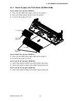
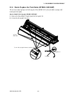
(1) Detach the right and left side covers (see Subsection 6.1.1 and Subsection 6.1.2).
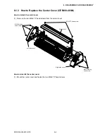
(2) Detach the center cover (see Subsection 6.1.3 or 6.1.4).
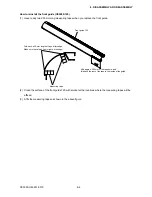
(3) Set the cam lever to the media release position.
(4) Remove the two M3L6 binding head screws attaching the cam lever.
Cam lever
Push roller arm spring
Cam shaft
Left cam shaft holder
M3L6 binding head screw
M3L6 binding head screw
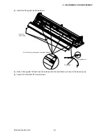
(5) Remove the M3L6 binding head screw attaching the left side cam shaft holder.
(6) Remove the two M3L6 binding head screws attaching the cam sensor plate to the cam shaft.
Cam sensor plate
M3L6 binding head screw
Содержание CE5000-120
Страница 1: ...CE5000 UM 251 09 9370 CE5000 Series SERVICE MANUAL MANUAL NO CE5000 UM 251 CUTTING PLOTTER...
Страница 24: ......
Страница 28: ...CE5000 UM 251 9370 3 4 3 OPERATIONS CE5000 120AP ENTER key ENTER key...
Страница 34: ......
Страница 36: ......
Страница 72: ......
Страница 90: ......
Страница 96: ......
Страница 100: ......
Страница 102: ...CE5000 UM 251 9370 10 2 10 PARTS LIST Outer Casing 1 2 3 4 5 8 6 7 9 10 13 11 12 14 15 16 18 17 19 20 21...
Страница 116: ......


