


CE5000-UM-251-9370
6-1
6. DISASSEMBLY AND REASSEMBLY
6. DISASSEMBLY AND REASSEMBLY
6.1 Exterior Parts
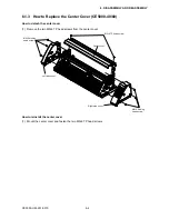
6.1.1 How to Replace the Right Side Cover
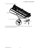
How to detach the right side cover
(1) Remove the three M4L6 binding head screws from the right side cover.
Note: Hold the right side cover after you have detached the screws; there is a flexible cable inside the cover.
(2) Disconnect the flexible cable which is connected to the control panel relay board.
Center cover
M3L6 TP head screw
M4L6 binding
head screw
Right side cover
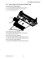
Left side cover
M4L6 binding
head screw
How to reinstall the right side cover
(1) Connect the flexible cable to the control panel relay board, and mount the right side cover.
(2) Fasten the three M4L6 binding head screws.
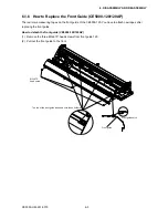
6.1.2 How to Replace the Left Side Cover
How to detach the left side cover
(1) Remove the three M4L6 binding head screws from the left side cover.
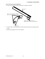
How to reinstall the left side cover
(1) Fasten the three M4L6 binding head screws.
Содержание CE5000-120
Страница 1: ...CE5000 UM 251 09 9370 CE5000 Series SERVICE MANUAL MANUAL NO CE5000 UM 251 CUTTING PLOTTER...
Страница 24: ......
Страница 28: ...CE5000 UM 251 9370 3 4 3 OPERATIONS CE5000 120AP ENTER key ENTER key...
Страница 34: ......
Страница 36: ......
Страница 72: ......
Страница 90: ......
Страница 96: ......
Страница 100: ......
Страница 102: ...CE5000 UM 251 9370 10 2 10 PARTS LIST Outer Casing 1 2 3 4 5 8 6 7 9 10 13 11 12 14 15 16 18 17 19 20 21...
Страница 116: ......


