12.2 BURNER FAULT INDICATION
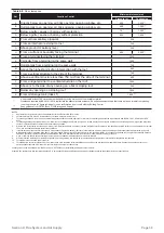
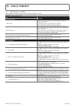
Whenever a burner lockout occurs the cause is displayed via the reset push button indicator LED on the control box. The colour, se-
quence and speed of the indicator LED flashes identify the specific lockout type and the possible causes are listed in Table 12-2.
Table 12-2:
Burner fault indication
Lockout description
Lockout time
LED colour
Probable cause
Presence of extraneous light during
standby
After 25 seconds
RED
blinking
• Presence of a false flame signal before the heat
request
Presence of extraneous light
detected during pre-purging
After 25 seconds
RED
blinking
• Presence of false flame signal during pre-purging
Extraneous light detected during
post-purging
After 25 seconds
RED
blinking
• Presence of false flame signal during post-
purging (or pre-heating if the short-circuit socket is
not connected
The flame is not detected after the
safety time
After 5 seconds from oil-valve starts
RED
steady ON
• UV sensor defective or dirty
• Oil valve defective or dirty
• Faulty ignition transformer
• Badly regulated burner
• Oil fuel not present
Flame failure during operation
After 3 recycles
RED
blinking
• Badly adjusted burner
• Oil valve defective or dirty
• UV sensor defective or dirty
Fan motor error
Immediate (during pre-purge)
RED, ORANGE
blinking inverted
• Faulty fan motor
• Fan motor not connected
Malfunction in the internal control
circuit that drives the oil valve
Immediate (during pre-purge)
RED, GREEN
blinking inverted
• Faulty oil valve
• Internal control circuit that drives the oil valve
faulty
Eeprom error
Immediate (during pre-purge)
ORANGE,
GREEN
blinking inverted
• Faulty internal memory
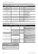
12.3 BURNER FAULT DIAGNOSTICS
Table 12-3:
Burner faults
Faults
Possible cause
Fault
diagnostics
Solutions
The burner does not start when there
is heat demand
Lack of electrical supply
OFF
Check presence of voltage in the L - N of the four
pin plug
Check the conditions of the fuses.
Check that safety thermostat is not in lockout
The UV sensor sees an extraneous
light
GREEN, RED
blinking
Eliminate the extraneous light.
The connections in the control box
are wrongly inserted
OFF
Check and connect all the plugs and sockets
properly.
The burner goes into lockout mode
before or during the pre-purging
The UV sensor sees extraneous light
RED blinking
Eliminate the extraneous light.
Burner runs normally in the pre-purge
and ignition cycle and locks out after
about 5 seconds
The UV sensor is dirty
RED steady ON
Clean
it
The UV sensor is faulty
Replace it
Flame moves away or fails
Check pressure and output of the fuel
Check air output
Change nozzle
Check the coil of solenoid valve
Burner starts with an ignition delay
The ignition electrodes are wrongly
positioned
GREEN blinking
Adjust them according to the instructions of this
manual
Air output is too high
Set the air output according to the instructions of
this manual
Nozzle dirty or worn
Replace it
Section 12: Fault Finding
Page 48
! NOTE !
For an overview of the fault diagnostic capabilities built
into the circulating pumps that come installed in the sealed
system boiler models, please refer to Appendix A2 or A3,
as required, at the back of this installation and servicing
manual.

