

Section 9: Flue System and Air Supply
Page 37
9.5
PREPARE THE WALL
9.5
PREPARE THE WALL
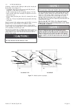
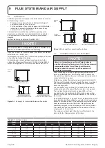
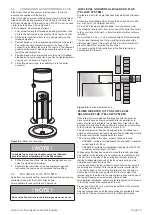
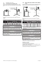
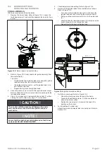
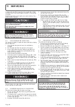
9.5.1 LOW LEVEL BALANCED FLUE
9.5.1 LOW LEVEL BALANCED FLUE
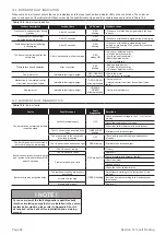
If the boiler is to be used with a low level balanced flue (Yellow
If the boiler is to be used with a low level balanced flue (Yellow
system) make the hole in the wall for the flue as shown in Figure
system) make the hole in the wall for the flue as shown in Figure
9-11.
9-11.
Side
wall
Rear wall
Note:
This dimension is given with
the boiler pushed back against
the rear wall. Any clearances
must be added to it.
Hole to be
cut in wall
Boiler
centre line
Outline
of boiler
Rear exit
Side exit
C
C
A
A
B
Figure 9-11:
Flue hole dimensions and position for low level
system
Table 9-6:
Low level balanced flue hole cutting dimensions
Model
Dimension (mm)
A (dia.)
B
C
21 & 26
127
120
764
36
162
120
786
! NOTE !
Dimension A given in Table 9-6 includes an extra 10 mm
over the size of the terminal to provide clearance for fitting.
! NOTE !
Dimension C given in Table 9-6 includes the depth of the
neoprene gasket on top of the heat exchanger when fully
compressed to 2mm.
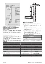
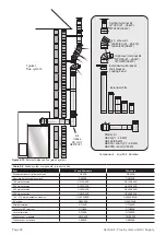
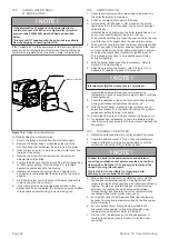
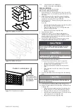
9.5.2 HIGH LEVEL AND VERTICAL BALANCED
9.5.2 HIGH LEVEL AND VERTICAL BALANCED
FLUE
FLUE
If the boiler is to be used with the high level balanced flue (White
If the boiler is to be used with the high level balanced flue (White
system) make the hole in the wall as shown in Figure 9-12.
system) make the hole in the wall as shown in Figure 9-12.
Side
wall
Rear wall
Note:
This dimension is given with
the boiler pushed back against
the rear wall. Any clearances
must be added to it.
Hole to be
cut in wall
Hole to be
cut in wall
Boiler
centre line
Outline
of boiler
Rear exit
Side exit
Standard kit with no extensions
D
C
A
A
B
Figure 9-12:
Flue hole dimensions and position for high level
system
Table 9-7:
High level balanced flue hole cutting dimensions
Model
Dimension (mm)
A (dia.)
B
C
D
21 and 26
175
120
1,229*
1,739 -
2,134**
36
200
120
1,281*
1,716 -
2016**
* Dimension C for starter section and elbow/terminal only
** Dimension D starter section, adjustable extension and elbow/terminal from
white system only
! NOTE !
Dimension A given in Table 9-7 includes an extra 10 mm
over the size of the terminal to provide clearance for fitting.
! NOTE !
Dimensions C and D given in Table 9-7 include the depth
of the neoprene gasket on top of the heat exchanger when
fully compressed to 2mm.
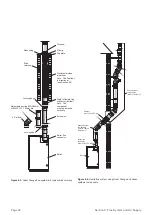
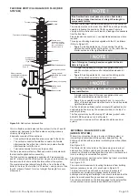
Fitting instructions for the high level balanced flue and vertical
Fitting instructions for the high level balanced flue and vertical
balanced flue are supplied with the flue kits.
balanced flue are supplied with the flue kits.
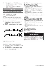
Adjustable extensions
Adjustable extensions
The adjustable extensions are telescopic.
The adjustable extensions are telescopic.
The wall terminal section is adjustable and is suitable for a wall
The wall terminal section is adjustable and is suitable for a wall
thickness of 215 mm to 450 mm.
thickness of 215 mm to 450 mm.
Simply adjust to the required length using a twisting motion. The
Simply adjust to the required length using a twisting motion. The
outer pipes must overlap by a minimum of 25 mm.
outer pipes must overlap by a minimum of 25 mm.


