background image


62

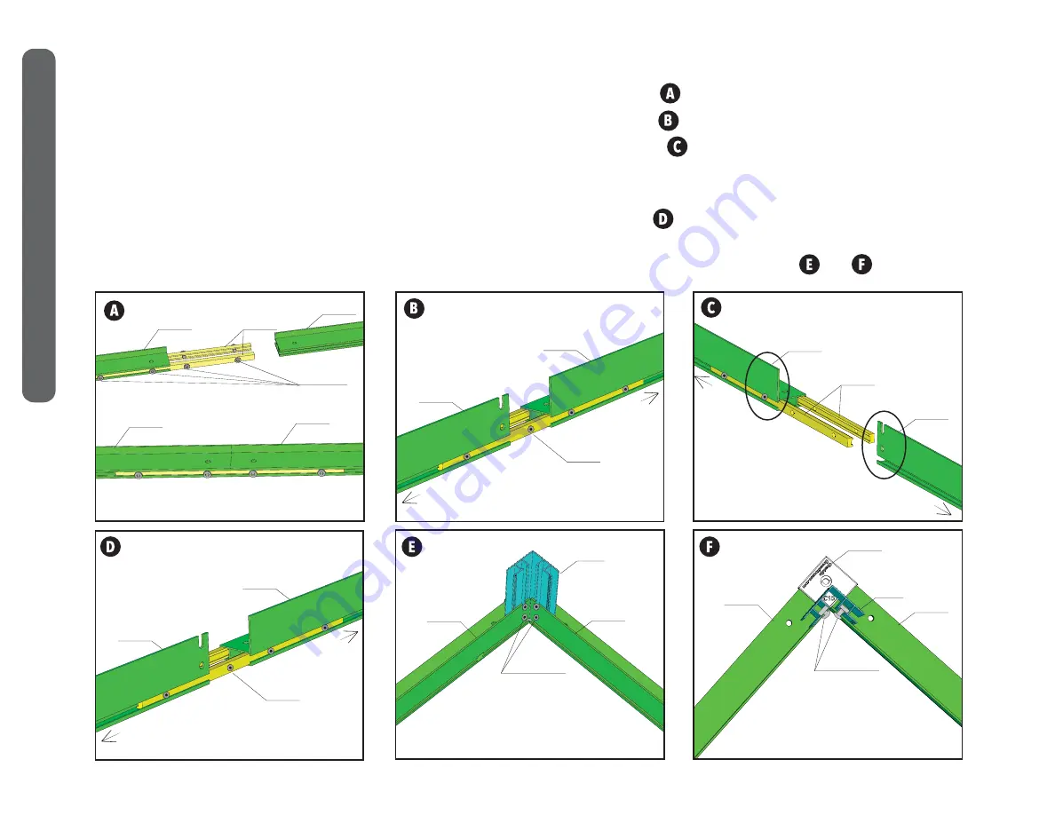
2. Connect the FRONT 12A and 12B pieces using the 14’s and the AFS-68 screws. See diagram          .
3. Connect the BACK section 12C and 12D using the 14’s and the AFS-68 screws. See diagram          .
4. Connect the RIGHT side 12C with the 12G using the 14’s and the AFS-68 screws, see diagram         .  Repeat connecting the 12G with the 12G, 

and 12G with 12E.
*REFER TO LAYOUT DIAGRAM ON PREVIOUS PAGE AS NEEDED.     
5. Connect the LEFT side 12C with the 12F using the 14’s and the AFS-68 screws, see diagram        . Repeat connecting the 12F with the 12F, and 

12F with 12D. 
6. Assemble the base kit as shown using the ABS-610 screws with the SQ-NUT-6 nuts at the 1C corners.  See diagrams         and         .

12B

14

12A

FRONT EXTERIOR VIEW

CONNECTION OF 14 PARTS WITH SCREWS

AFS-68

FRONT

12A

12B

GRANDIO SUMMIT 12x28 FLAT MOUNT BASE ASSEMBLY

BACK INTERIOR VIEW

12C

12D

14

LEFT

RIGHT

LEFT INTERIOR VIEW

12C

12F

14

FRONT

BACK

INTERIOR CORNER VIEW

OF THE FLAT MOUNT BASE KIT

12D

12E

1C

ABS-610

SQ-NUT-6

BIRDS EYE CORNER VIEW

OF THE FLAT MOUNT BASE KIT

12D

12E

C15

1C

ABS-610

SQ-NUT-6

12C

12G

14

RIGHT SIDE INTERIOR VIEW

FRONT

BACK

12X28 FLA

T MOUNT

 BASE

Содержание GRA-BASE-S128

Страница 1: ...LATION WARNINGS CHOOSING YOUR SURFACE BASE KIT ASSEMBLY INSTRUCTIONS SECURING BASE KIT TO SURFACE FOR ALL SIZES WARRANTY G R E E N H O U S E S GRANDIO 2018 Grandio Greenhouses Backyard Living Source I...

Страница 2: ...lacement BASE KIT PARTS LISTS quick reference for base kit assemblies CHAPTER 1 12x8 Greenhouse Dimensions Base Kit Installation Instructions CHAPTER 2 12x12 Greenhouse Dimensions Base Kit Installatio...

Страница 3: ...andio Greenhouse will be covered on your policy Call your local utilities companies before digging Do not attempt to begin construction on a windy day plan to complete assembly in one day Damage cause...

Страница 4: ...we recommend marking a small x on a corner of each panel to determine which side has the UV Coating as you cannot visually determine with your eye in the case of future disassembly Due to shipping th...

Страница 5: ...aying all of your boxes out as shown on the graphic below for an organized assembly Locate your greenhouse size and situate your boxes near your assembly site as shown in the order listed below Invent...

Страница 6: ...ive in a windy location there is no way to build a 100 storm safe greenhouse but there are a number of things you can do to minimize the chance of damage Ensure that the base is level and square be su...

Страница 7: ...FM 4 EXTENSION RIGHT 93 7 16 in 2374 mm FM 8 EXTENSION LEFT 93 7 16 in 2374 mm FM 8 EXTENSION RIGHT 11 3 16 300 mm 609 CONNECTOR ALLEN FLANGED SCREW 6 8 FM BASE CORNER GUARD 100MM CORNER PIECE FOR AL...

Страница 8: ...AGE BOLT 6 10 FLANGED NUT MID BRACKET FOR BASE 5 7 16 in 138 mm END BRACKET FOR BASE 3 15 16 in 100 mm 12 EARTH ANCHOR 1 2 x 3 4 COMBOS FOR ATTACHING FLAT MOUNT TO THE STEEL BASE 0 2 2 2 0 52 52 2 4 1...

Страница 9: ...94 25 L Door Dimensions 41 5 W x 85 25 H Bottom Side of Gutter Height 57 H Peak Roof Height 111 H 12x8 Grandio Summit with Steel Base Kit Dimensions The Steel Base Kit is sold separately from the Summ...

Страница 10: ...hen attach the Flat Mount Kit onto your Steel Base Kit The Flat Mount Kit will be assembled as shown in this section then secured to the surface of your choice using the proper anchoring hardware You...

Страница 11: ...oors to be located Be sure the pieces are laid out exactly like the diagram note that notches will have a 23 gap between each other no notches should be right next to each other except at the corners...

Страница 12: ...BS 610 screws with the SQ NUT 6 nuts at the 1C corners See diagrams and 12B 14 12A FRONT EXTERIOR VIEW CONNECTION OF 14 PARTS WITH SCREWS AFS 68 FRONT 12A 12B GRANDIO SUMMIT 12x8 FLAT MOUNT BASE ASSEM...

Страница 13: ...instructions that come with your anchoring kit Drill the holes into your surface blow out the debris then install the screws Keep the Left side 12C and the Right side 12C in place with the anchors in...

Страница 14: ...is not included purchase at a local hardware store The side sections of the Flat Mount Base Kit will attach on top of the Steel Base Kit prior to earth install the front and back walls must be assembl...

Страница 15: ...shown in the diagram below failure to assemble exactly as shown will cause problems later in assembly 2 Con rm that the small oval holes are all on the top side of the base kit and the large round ho...

Страница 16: ...610 ML01 CB 610 ML01 3 Use the CB 610 bolts with the ML01 nuts to assemble the steel base kit as shown in diagrams and at the bottom of this page Note the CB 610 s will be on the outside and the ML01...

Страница 17: ...ghten the hardware using the W16 10 mm Wrench and W17 Allen Driver Set aside the Front and Back sections of the Flat Mount Base these sections will be required to assemble the front and back walls in...

Страница 18: ...then mark the ground where the BA A1 L Bolts will reside with a marking paint You will then move base aside in order to dig out the holes 2 Dig out the holes for the BA A1 anchors then con rm the base...

Страница 19: ...Door Dimensions 41 5 W x 85 25 H Bottom Side of Gutter Height 57 H Peak Roof Height 111 H 12x12 Grandio Summit with Steel Base Kit Dimensions The Steel Base Kit is sold separately from the Summit Gree...

Страница 20: ...ch the Flat Mount Kit onto your Steel Base Kit The Flat Mount Kit will be assembled as shown in this section then secured to the surface of your choice using the proper anchoring hardware You will dri...

Страница 21: ...ve a 23 gap between each other no notches should be right next to each other except at the corners See and to con rm you have the correct orientation prior to assembly Note The 12D and 12E pro les may...

Страница 22: ...AFS 68 screws see diagram 6 Assemble the base kit as shown using the ABS 610 screws with the SQ NUT 6 nuts at the 1C corners See diagrams and 12B 14 12A FRONT EXTERIOR VIEW CONNECTION OF 14 PARTS WIT...

Страница 23: ...th your anchoring kit Drill the holes into your surface blow out the debris then install the screws Keep the Left side 12C and 12D and the Right side 12C and 12E in place with the anchors installed an...

Страница 24: ...purchase at a local hardware store The side sections of the Flat Mount Base Kit will attach on top of the Steel Base Kit prior to earth install the front and back walls must be assembled using the fro...

Страница 25: ...as shown in the diagram below failure to assemble exactly as shown will cause problems later in assembly 2 Con rm that the small oval holes are all on the top side of the base kit and the large round...

Страница 26: ...10 ML01 CB 610 ML01 3 Use the CB 610 bolts with the ML01 nuts to assemble the steel base kit as shown in diagrams and at the bottom of this page Note the CB 610 s will be on the outside and the ML01 n...

Страница 27: ...ide the Front and Back sections of the Flat Mount Base these sections will be required to assemble the front and back walls in Manual 2 Note The 12D and 12E pro les may be labeled incorrectly on this...

Страница 28: ...e aside in order to dig out the holes 2 Dig out the holes for the BA A1 anchors then con rm the base is square and level again with the base kit moved back into place and BA A1 s in their respective h...

Страница 29: ...el Base Kit is sold separately from the Summit Greenhouse Kit and is designed to be installed directly into the Earth using the included L Bolts which must be secured into Quikrete or a similar concre...

Страница 30: ...ttach the Flat Mount Kit onto your Steel Base Kit The Flat Mount Kit will be assembled as shown in this section then secured to the surface of your choice using the proper anchoring hardware You will...

Страница 31: ...eces are laid out exactly like the diagram note that notches will have a 23 gap between each other no notches should be right next to each other except at the corners See and to con rm you have the co...

Страница 32: ...AFS 68 screws see diagram 6 Assemble the base kit as shown using the ABS 610 screws with the SQ NUT 6 nuts at the 1C corners See diagrams and 12B 14 12A FRONT EXTERIOR VIEW CONNECTION OF 14 PARTS WIT...

Страница 33: ...th your anchoring kit Drill the holes into your surface blow out the debris then install the screws Keep the Left side 12C and 12F and the Right side 12C and 12G in place with the anchors installed an...

Страница 34: ...Quikrete or a similar concrete material NOTE concrete is not included purchase at a local hardware store The side sections of the Flat Mount Base Kit will attach on top of the Steel Base Kit prior to...

Страница 35: ...Kit exactly as shown in the diagram below failure to assemble exactly as shown will cause problems later in assembly 2 Con rm that the small oval holes are all on the top side of the base kit and the...

Страница 36: ...10 ML01 CB 610 ML01 3 Use the CB 610 bolts with the ML01 nuts to assemble the steel base kit as shown in diagrams and at the bottom of this page Note the CB 610 s will be on the outside and the ML01 n...

Страница 37: ...the hardware using the W16 10 mm Wrench and W17 Allen Driver Set aside the Front and Back sections of the Flat Mount Base these sections will be required to assemble the front and back walls in Manua...

Страница 38: ...2 Dig out the holes for the BA A1 anchors then con rm the base is square and level again with the base kit moved back into place and BA A1 s in their respective holes Check with your local building c...

Страница 39: ...rom the Summit Greenhouse Kit and is designed to be installed directly into the Earth using the included L Bolts which must be secured into Quikrete or a similar concrete material The Flat Mount Base...

Страница 40: ...ttach the Flat Mount Kit onto your Steel Base Kit The Flat Mount Kit will be assembled as shown in this section then secured to the surface of your choice using the proper anchoring hardware You will...

Страница 41: ...ill have a 23 gap between each other no notches should be right next to each other except at the corners See and to con rm you have the correct orientation prior to assembly Note The 12D and 12E pro l...

Страница 42: ...AFS 68 screws see diagram Repeat connecting the 12F with the 12D 6 Assemble the base kit as shown using the ABS 610 screws with the SQ NUT 6 nuts at the 1C corners See diagrams and 12B 14 12A FRONT E...

Страница 43: ...our anchoring kit Drill the holes into your surface blow out the debris then install the screws Keep the Left side 12C 12F and 12D and the Right side 12C 12G and 12E in place with the anchors installe...

Страница 44: ...rchase at a local hardware store The side sections of the Flat Mount Base Kit will attach on top of the Steel Base Kit prior to earth install the front and back walls must be assembled using the front...

Страница 45: ...e Kit exactly as shown in the diagram below failure to assemble exactly as shown will cause problems later in assembly 2 Con rm that the small oval holes are all on the top side of the base kit and th...

Страница 46: ...10 ML01 CB 610 ML01 3 Use the CB 610 bolts with the ML01 nuts to assemble the steel base kit as shown in diagrams and at the bottom of this page Note the CB 610 s will be on the outside and the ML01 n...

Страница 47: ...he Front and Back sections of the Flat Mount Base these sections will be required to assemble the front and back walls in Manual 2 Note The 12D and 12E pro les may be labeled incorrectly on this produ...

Страница 48: ...ase is square and level again with the base kit moved back into place and BA A1 s in their respective holes Check with your local building code for depth requirements 3 We recommend you use a concrete...

Страница 49: ...rom the Summit Greenhouse Kit and is designed to be installed directly into the Earth using the included L Bolts which must be secured into Quikrete or a similar concrete material The Flat Mount Base...

Страница 50: ...Kit will be assembled as shown in this section then secured to the surface of your choice using the proper anchoring hardware You will drill all holes into your surface for the entire base kit and tem...

Страница 51: ...the pieces are laid out exactly like the diagram note that notches will have a 23 gap between each other no notches should be right next to each other except at the corners See and to con rm you have...

Страница 52: ...AFS 68 screws see diagram Repeat connecting the 12F with the 12F 6 Assemble the base kit as shown using the ABS 610 screws with the SQ NUT 6 nuts at the 1C corners See diagrams and 12B 14 12A FRONT E...

Страница 53: ...our anchoring kit Drill the holes into your surface blow out the debris then install the screws Keep the Left side 12C 12F and 12F and the Right side 12C 12G and 12G in place with the anchors installe...

Страница 54: ...ust be secured with Quikrete or a similar concrete material NOTE concrete is not included purchase at a local hardware store The side sections of the Flat Mount Base Kit will attach on top of the Stee...

Страница 55: ...arts for your Steel Base Kit exactly as shown in the diagram below failure to assemble exactly as shown will cause problems later in assembly 2 Con rm that the small oval holes are all on the top side...

Страница 56: ...10 ML01 CB 610 ML01 3 Use the CB 610 bolts with the ML01 nuts to assemble the steel base kit as shown in diagrams and at the bottom of this page Note the CB 610 s will be on the outside and the ML01 n...

Страница 57: ...hardware using the W16 10 mm Wrench and W17 Allen Driver Set aside the Front and Back sections of the Flat Mount Base these sections will be required to assemble the front and back walls in Manual 2...

Страница 58: ...es are level then mark the ground where the BA A1 L Bolts will reside with a marking paint You will then move base aside in order to dig out the holes 2 Dig out the holes for the BA A1 anchors then co...

Страница 59: ...from the Summit Greenhouse Kit and is designed to be installed directly into the Earth using the included L Bolts which must be secured into Quikrete or a similar concrete material The Flat Mount Base...

Страница 60: ...will follow these instructions to assemble the Flat Mount section but will then attach the Flat Mount Kit onto your Steel Base Kit The Flat Mount Kit will be assembled as shown in this section then s...

Страница 61: ...e front is where you want your doors to be located Be sure the pieces are laid out exactly like the diagram note that notches will have a 23 gap between each other no notches should be right next to e...

Страница 62: ...AFS 68 screws see diagram Repeat connecting the 12F with the 12F and 12F with 12D 6 Assemble the base kit as shown using the ABS 610 screws with the SQ NUT 6 nuts at the 1C corners See diagrams and 1...

Страница 63: ...anchoring kit Drill the holes into your surface blow out the debris then install the screws Keep the Left side 12C 12F 12F and 12D and the Right side 12C 12G 12G and 12E in place with the anchors inst...

Страница 64: ...om the Summit Greenhouse Kit and is to be installed directly into the Earth using the included L Bolts which must be secured with Quikrete or a similar concrete material NOTE concrete is not included...

Страница 65: ...FT 1 Lay out all the parts for your Steel Base Kit exactly as shown in the diagram below failure to assemble exactly as shown will cause problems later in assembly 2 Con rm that the small oval holes a...

Страница 66: ...10 ML01 CB 610 ML01 3 Use the CB 610 bolts with the ML01 nuts to assemble the steel base kit as shown in diagrams and at the bottom of this page Note the CB 610 s will be on the outside and the ML01 n...

Страница 67: ...NSTALLATION 1 Attach the side Flat Mount Base pieces to the Steel Base Kit as shown below using the ABS 625 screws with the ML01 nuts See and Tighten the hardware using the W16 10 mm Wrench and W17 Al...

Страница 68: ...heck that all sides are level then mark the ground where the BA A1 L Bolts will reside with a marking paint You will then move base aside in order to dig out the holes 2 Dig out the holes for the BA A...

Страница 69: ...from the Summit Greenhouse Kit and is designed to be installed directly into the Earth using the included L Bolts which must be secured into Quikrete or a similar concrete material The Flat Mount Base...

Страница 70: ...will follow these instructions to assemble the Flat Mount section but will then attach the Flat Mount Kit onto your Steel Base Kit The Flat Mount Kit will be assembled as shown in this section then s...

Страница 71: ...parts exactly as shown in the diagram below Con rm that the front is where you want your doors to be located Be sure the pieces are laid out exactly like the diagram note that notches will have a 23...

Страница 72: ...AFS 68 screws see diagram Repeat connecting the 12F with the 12F and 12F with 12F 6 Assemble the base kit as shown using the ABS 610 screws with the SQ NUT 6 nuts at the 1C corners See diagrams and 1...

Страница 73: ...anchoring kit Drill the holes into your surface blow out the debris then install the screws Keep the Left side 12C 12F 12F and 12F and the Right side 12C 12G 12G and 12G in place with the anchors inst...

Страница 74: ...ectly into the Earth using the included L Bolts which must be secured with Quikrete or a similar concrete material NOTE concrete is not included purchase at a local hardware store The side sections of...

Страница 75: ...your Steel Base Kit exactly as shown in the diagram below failure to assemble exactly as shown will cause problems later in assembly 2 Con rm that the small oval holes are all on the top side of the...

Страница 76: ...10 ML01 CB 610 ML01 3 Use the CB 610 bolts with the ML01 nuts to assemble the steel base kit as shown in diagrams and at the bottom of this page Note the CB 610 s will be on the outside and the ML01 n...

Страница 77: ...ACHING THE FLAT MOUNT BASE TO THE STEEL BASE KIT FOR EARTH INSTALLATION 1 Attach the side Flat Mount Base pieces to the Steel Base Kit as shown below using the ABS 625 screws with the ML01 nuts See an...

Страница 78: ...will then move base aside in order to dig out the holes 2 Dig out the holes for the BA A1 anchors then con rm the base is square and level again with the base kit moved back into place and BA A1 s in...

Страница 79: ...ated expenses for removal installation or replacement of the greenhouse or its components are not covered under this warranty 4 This warranty does not cover scratching or scuf ng of the product that m...

Страница 80: ...ASE KIT SEE INSTALLATION MANUAL 2 GREENHOUSE ASSEMBLY SEE PARTS LIST MANUAL 3 PARTS LIST G R E E N H O U S E S GRANDIO Save this owner s manual for future reference and if you need our help CONTACT OU...

Отзывы: