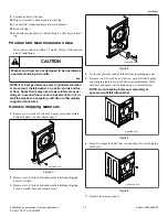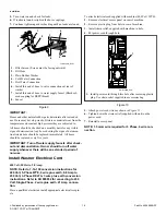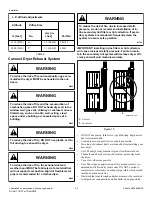
Vertical Exhaust Installation
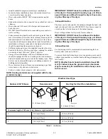
D753I_SVG
7
2
6
5
4
3
1
1.
Roof
2.
610 mm [24 in.] Minimum Clearance to Roof/Ground
3.
No Screen or Cap
4.
Wall
5.
50 mm [2 in.] Minimum
6.
Where the exhaust duct pierces a combustible wall or ceil-
ing, an opening must be sized as shown or per local codes.
7.
Connect to Dryer
Figure 18
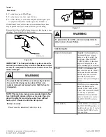
WARNING
To reduce the risk of fire and the accumulation of
combustion gases, DO NOT exhaust dryer air into a
window well, gas vent, chimney or enclosed, unven-
tilated area, such as an attic, wall, ceiling, crawl
space under a building or concealed space of a
building.
W045
A Backdraft Damper should be installed in a 102 mm [4 inch]
diameter VERTICAL duct system. This will prevent a backdraft
when dryer is not in use, and will keep the exhaust air in balance
within the central exhaust system.
Position and Level the Unit
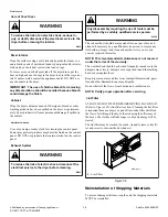
WARNING
Units elevated above floor level must be anchored to
that elevated surface, base or platform. The material
used to elevate the unit should also be anchored to
the floor to ensure that the unit will not walk or that
the unit can not be physically pulled, tipped or slid
from its installed position. Failure to do so may re-
sult in conditions which can produce serious injury,
death and/or property damage.
W307
1.
Position unit so it has sufficient clearance for installation and
servicing.
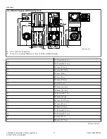
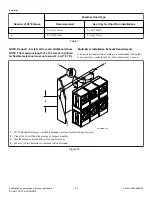
SWD1006N_SVG
C
E
E
A
B
D
NOTE: Shaded areas indicate adjacent structure.
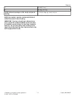
Dryer and Exhaust Duct Clearances
Area
Description
Minimum
Clearance
A
Left Dryer Side
0 mm [0 in.]
B
Right Dryer Side 25 mm [1 in.]
C
Dryer Top
152 mm [6 in.]
D *
Dryer Rear
102 mm [4 in.]
E
Exhaust Duct
Clearance to
Combustible Ma-
terials
51 mm [2 in.]
Table continues...
Installation
©
Published by permission of the copyright owner -
DO NOT COPY or TRANSMIT
26
Part No. 805898ENR1

