


8
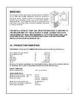
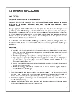
3.0 FURNACE INSTALLATION
GAS PIPING
Gas piping must conform to local requirements.
Install according to the applicable code such as NATIONAL FUEL GAS CODE ANDSI
Z223.1/NFPA 54 AND/OR NATIONAL GAS AND PROPANE INSTALLATION CODE
CAN/CSA B149.1.
The gas piping must be installed between the gas meter and the combination gas valve
(located upstream of the Riello gas burner on the furnace. The gas valve has a knob acting as
a shut-off valve to stop gas flow. It is recommended to install a manual shut-off valve upstream
of the gas valve to facilitate service of the gas valve. The gas valve also has pressure tapping
for inlet pressure as well as outlet pressure. The outlet pressure of the gas valve is also
referred as manifold pressure in this manual.
If local codes allow the use of a flexible gas appliance connector, always use a new
listed connector. Do not use a connector which has previously serviced another gas
appliance
WARNING:
•
Connect from the gas supply to the burner combination gas valve inlet using new, clean
black iron pipe and malleable iron fittings only. Do not use copper, brass, cast iron or
galvanized pipe or fittings.
•
Provide support for gas piping. Do not rest weight of piping on burner gas valve.
•
Apply pipe dope sparingly at all joints. Use only pipe dope listed for use with propane
gas. Do not use pipe sealing tape. In doubt consult CSA B149.1 or NFPA 54 or the
authorities having jurisdiction.
•
Do not hold gas valve with a pipe wrench. Use crescent wrench or other smooth jawed
device. Do not over-tighten.
•
Failure to comply with above could result in severe personal injury, death or
substantial property damage.
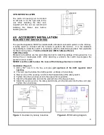
1. If possible, install a new gas line directly from the gas meter. If you are using an existing
gas line, verify it is clean and in good condition and verify it is large enough to handle the
load of all connected appliances. See the table below for guidance on pipe sizes.
2. When branching from a common gas line, do not tap from the bottom or horizontal sections,
only from the side or top.
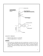
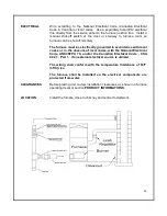
3. Install a main manual shutoff valve, sediment trap and ground joint union near the burner
combination gas valve connection as shown below.


