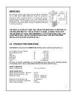
Granby KHM SERIES Скачать руководство пользователя страница 14

13 


Connecting non-metallic vent pipe and fittings with thermal insulation shall be prohibited. 

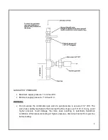
Horizontal  portions  of  the  venting  system  shall  be  supported  to  prevent  sagging  by  installing 
support every 36 inches. The horizontal runs must be sloping upwards not less than ¼ inch per 
foot from the boiler to the chimney connector. 

A furnace shall not be connected to a chimney flue serving a separate appliance designed to 
burn solid fuel. 

Provisions for adequate combustion and ventilation air shall be in accordance with one of the 
following: 

1.  Section  5.3,  Air  for  Combustion  and  Ventilation,  of  the  National  Fuel  Gas  Code,  ANSI 
Z223.1/NFPA 54 , 

2. Sections 7.2, 7.3 or 7.4 of Natural Gas and Propane Installation Code, CSA B149.1 , 

3. Applicable provisions of the local building code. 
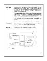
 

CONDENSATION 

If  you  have  condensation  in  your  chimney,  make  sure  that  the 
chimney  size  is  according  to  the  tables  in  THE  NATIONAL  FUEL 
GAS  CODE  ANDSI  Z223.1/NFPA  54  AND/OR  NATIONAL  GAS  AND 
PROPANE 

INSTALLATION 

CODE 

CAN/CSA 

B149.1. 

The 

temperature  at  the  entrance  of  the  chimney  can  be  increased  by 
insulating the flue-pipe between the furnace and the chimney base.  
If  this  is  not  sufficient,  consider  cutting  or  removing  some  flue 
baffles in the furnace.   

 
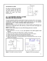
CHIMNEY/VENT
       Furnace is approved for factory built chimney type “L” vents.  Breech is 

certified for 5” vent pipe.  Keep vent/flue pipe as short as possible with a 
minimum upward slope of ¼’’ per foot.  Vent/flue pipes MUST NOT pass 
through a ceiling.  Maximum flue gas temperature is 575°F. 


COMBUSTION &


Install openings and ductwork to the  furnace   room  providing  fresh 

VENTILATION AIR  outside combustion and circulation air for cooling the furnace casing, as 

installation code requires.  If installed in a closed room, provide two free 
air ventilation openings of at least 8” x 12” (96 sq. in.) free flow area near 
ceiling  and  floor.  Gas  burners  must  have  sufficient  air  to  allow  vent 
systems to operate properly. 
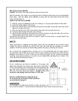


DRAFT 

Use approved DOUBLE ACTING draft control supplied for 5” pipe.  Set 
specified  draft  minimum  pressure  of  -0.01”  wc.  THE  CHIMNEY  MUST 
BE  EQUIPPED  WITH  A  DOUBLE  ACTING  DRAFT  REGULATOR. 
FAILURE  TO  COMPLY  WITH  THIS  MAY  RESULT  IN  IMPROPER 
OPERATION  LEADING  TO  POTENTIAL  DANGEROUS  OPERATION 
OF UNIT AND INJURIES TO PERSON AND LOSS OF LIFE. 


Содержание KHM SERIES

Страница 1: ...TIONS MUST MEET ALL LOCAL AND FEDERAL CODES THAT MAY DIFFER FROM THIS MANUAL Please read the manual in its entirety before beginning installation This manual must be kept with the furnace for future r...

Страница 2: ...19 5 2 GAS FIRED FURNACE LIGHTING INSTRUCTIONS 20 5 2 TECHNICAL INFORMATION 21 6 0 FURNACE OPERATION AND SETTINGS 22 6 1 BLOWER SETTING 22 6 2 FAN TIMER CONTROL BOARD ST9103 A 1028 23 6 3 ST9103 A 102...

Страница 3: ...injury or death Do not store or use gasoline or other flammable vapors or liquid in the vicinity of this or any other appliance WHAT TO DO IF YOU SMELL GAS o Do not try to light the appliance o Do no...

Страница 4: ...tic pressure within the allowable range as specified in Section 5 of these instructions See furnace rating plate When a furnace is installed so that supply ducts carry air circulated by the furnace to...

Страница 5: ...s paint removers varnishes etc Hydrochloric acid Cements and glues Antistatic fabric softeners for clothes dryers Masonry acid washing materials WARNINGS NEVER burn garbage or paper in the unit NEVER...

Страница 6: ...NFPA 54 AND OR NATIONAL GAS AND PROPANE INSTALLATION CODE CAN CSA B149 1 2 0 PRODUCT INFORMATION CLEARANCE minimum TO COMBUSTIBLES Operation and Service Clearances Top Sides of Supply Plenum 1 25 mm...

Страница 7: ...457 x 457 mm Hot air supply B 20 x 20 508 x 508 mm PLENUM DIMENSIONS KHM 200 Cold air return A 23 x 18 584 x 457 mm Hot air supply B 24 x 20 610 x 508 mm AIR FILTERS KHM 100 20 x 20 x 2 Pleated UL app...

Страница 8: ...7 KHM 100 DIMENSIONS Dimensions are in inches KHM 200 DIMENSIONS Dimensions are in inches...

Страница 9: ...combination gas valve inlet using new clean black iron pipe and malleable iron fittings only Do not use copper brass cast iron or galvanized pipe or fittings Provide support for gas piping Do not rest...

Страница 10: ...mbination gas valve to gas pressures in excess of 14 W C The valve has a safety mechanism that interrupt the flow of gas over 14 W C In any event higher pressure could damage the valve seat resulting...

Страница 11: ...ion Enough combustion air should be provided to the gas fired furnace in accordance with the section Air for combustion and ventilation of the National Fuel Gas Code ANSI Z223 1 NFPA 54 or clause 8 2...

Страница 12: ...e poisoning or death When an existing furnace is removed from a common venting system the common venting system is likely to be too large for proper venting of the appliances connected to it At the ti...

Страница 13: ...g of Category I Venting Systems CSA B199 1 of the National Fuel Gas Code ANSI Z223 1 NFPA 54 and or Section 7 Venting Systems and Air Supply for Appliances and Appendix C Vent Sizing Tables for Catego...

Страница 14: ...the entrance of the chimney can be increased by insulating the flue pipe between the furnace and the chimney base If this is not sufficient consider cutting or removing some flue baffles in the furnac...

Страница 15: ...accordance with local codes or in the absence of local codes with the National Electrical Code ANSI NFPA 70 and or the Canadian Electrical Code CSA C22 1 Part 1 if an external electrical source is uti...

Страница 16: ...gas safety devices for detecting spillage of flue gases due to a blocked flue or inadequate draft After detecting a problem the switch de energizes the system s burner control NEVER reset the switch...

Страница 17: ...ace to areas outside the space containing the furnace the return air shall also be handled by a duct s sealed to the furnace casing and terminating outside the space containing the furnace For a furna...

Страница 18: ...ottom right side and under the furnace Follow the instructions below to install the air filter support properly Step 1 Slide air filter spacer inside the outside filter rack Step 2 Screw in the 4 scre...

Страница 19: ...t side right side or base panel where you want to install the air filter Step 6 Cut the panel between the 4 knockouts Step 7 Using 8 screws install the air filter rack on the furnace Step 8 Slide the...

Страница 20: ...ion in section 5 2 below o In the section Combustion head settings disregard the table and use the information in section 5 2 below o In the section Manifold pressures disregard the table and use the...

Страница 21: ...off valve that you closed a few steps back Press the red button on the ignition control The burner should then retry its ignition and light the burner If this sequence is not respected consult the bu...

Страница 22: ...11 0 Propane 9 8 Natural 11 6 Propane Efficiency 83 50 83 50 General Information Motor info Temperature Rise F 75 Max 0 5 W C Static Pr essure 75 Max 0 5 W C Static Pressure Static Pressure at 0 2 WC...

Страница 23: ...k that the furnace starts and operates as usual OPERATION If the furnace system fails to operate or operates in an unusual manner call your service technician If the burner fails to operate at any tim...

Страница 24: ...tlet air is too cold or too warm at the end of the heating cycle after the burner has turned off adjust the FAN OFF dip switch on electronic fan center Refer to the next figure FAN OFF Dip Switch OFF...

Страница 25: ...Burner shuts down after call for heat is satisfied 5 Blower stops according to adjusted FAN OFF Dip switch selection ST9103 Cooling Sequence 1 Thermostat calls for cooling 2 Blower starts immediately...

Страница 26: ...Move to next step No Check for bad connection Yes Move to next step No Change Transformer 3 Electronic Fan control Check for 24 Volts between R and C Yes Move to next step No Change the electronic bo...

Страница 27: ...p No Change the electronic fan control Check for 120 Volts on the contact No of the burner activation relay Yes Move to next step No Change the burner activation relay Check for 120 volts on the orang...

Страница 28: ...electronic fan control Yes Compressor ON No Check thermostat and wiring 9 Electronic air filter Check for 120 Volts on terminal EAC of the electronic fan control thermostat must call a Heat Cool or F...

Страница 29: ...ILTERS To maintain furnace performance and safety replace dirty filters as required or at least once every heating season or as required Use new approved disposable filters of the same size and type D...

Страница 30: ...off oil and power to furnace 2 Remove the two 2 screws securing the blower door Figure 1 3 Open blower compartment Figure 2 4 Disconnect the wiring to the blower motor 5 Remove the screw securing the...

Страница 31: ...manufacturer has supplied instructions for servicing and maintenance should be performed as instructed Riello 40 G120 Gas Burner Carlin EZGas PRO Burner Burner PERFORM COMBUSTION TEST Perform an annua...

Страница 32: ...31 8 0 ELECTRICAL WIRING DIAGRAMS HEATING COOLING Connection for Carlin Burner check the Carlin burner instruction manual...

Страница 33: ...32 9 0 EXPLODED PARTS VIEW KHM 100 Exploded Parts View KHM 100 Part List...

Страница 34: ...C SPDT 24V 1 17 4TF 00 40VA 00 Transformer HTC 01A0BB01 40 VA 1 18 FAN A0 0002 00 Fan Motor Assembly KLR 090 PSC Motor 1 19 FAN A0 0002 01 Fan Motor Assembly KLR 090 ECM Motor 1 20 3BU 10 08DD 00 Blow...

Страница 35: ...34 KHM 200 Part List...

Страница 36: ...4001 24VAC Form C SPDT 24V 1 17 4TF 00 40VA 00 Transformer HTC 01A0BB01 40 VA 1 18 FAN A0 0001 00 Fan Motor Assembly KHM 140 PSC Motor 1 19 FAN A0 0001 01 Fan Motor Assembly KHM 140 ECM Motor 1 20 3BU...

Страница 37: ...ULTS Size of unit Btu h Input __________________ Manifold pressure _____________ Chimney____________ Combustion Results CO2 Chimney draft W C Ambient temperature F Gross flue temperature F Temperature...

Страница 38: ...sure Reading A C Coil Total Resistance Reading Supply Pressure Ps Return Pressure Pr Coil Pressure Pc Supply Pressure Ps Temperature Rise Reading Supply Temp Ts Return Temp Tr Probe must not be in dir...

Страница 39: ...a and the United States through a distribution network Our team of engineers designers and technicians continually research and develop products to go beyond the demanding specifications of today s ce...

Отзывы: