background image


8

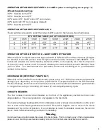
OPERATION OPTIONS DIP SWITCHES 1, 2, 3 AND 4

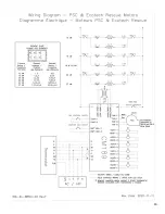
 (refer to wiring diagram on page 13)


DIP switches position settings

:


DIP 1:  Must be set to OFF 
DIP 2:  Must be set to OFF 
DIP 3 set to OFF: No HP coil or HP coil in return 
DIP 3 set to ON: HP Coil in supply (Default) 
DIP 4:  Must be set to OFF 


OPERATION OPTIONS DIP SWITCHES A, B, C 

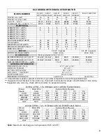
These switches are used to select the correct kW/H output of the furnace. See chart below.


BTU SETTING TABLE (DIP OPTION SWITCHES)


DIP


5KW


10KW


15KW


18KW


20KW


23KW


27KW


A


OFF


ON


OFF


ON


OFF


ON


OFF


B


OFF


OFF


ON


ON


OFF


OFF


ON


C


OFF


OFF


OFF


OFF


ON


ON


ON


OPERATION OPTION DIP SWITCH D - QUIET COMFORT FEATURE  

When the Quiet Comfort Feature has been activated at DIP switch D and the continuous circulation 
fan switch is in  the  ON  position, the LED light on the front of the furnace will flash AMBER.


This 

feature will activate one of the heating elements at 50% of its capacity for a maximum period 
of three (3) hours unless a call for heat is made by the thermostat, which will reset the three 
(3) hour timer.  The feature allows for preheated continuous circulating air to provide added 
comfort in the home.  


DEICING MODE (WITH HEAT PUMP ONLY) 

When this unit is installed in accordance with a heat pump unit.  While the heat control enters its 
deicing cycle, depending on the position of DIP Switch 3 (explained above in the DIP Switches 
Position Settings) the furnace control will activate one or more electric elements to generate heat 
to mitigate the cooling of circulating air caused by the heat pump deicing cycle. 
 

CIRCUIT BREAKERS 

The 16A furnace mounted circuit breaker on the front of the appliance provides fan motor over 
amp protection. This circuit protection only applies to the fan motor.


The higher amperage heating element circuit breaks provide overload circuit protection in the event 
one or more of the heating elements should fail. Should this happen, one or more of the circuit 
breakers  will  trip  to  the  off position.


Do  not  attempt  to  reset  the breaker  or access the  control 

panel. Call a licensed servicing contractor immediately.


Warning 

Do not use these circuit breakers the power off to the furnace.  Prior to removing any of the furnace access 
panels ensure that the power has been safely turned off at the main electrical disconnect switch. 


Содержание Conforto KLE 10 TO 27kW

Страница 1: ...E 10 TO 27kW INSTALLATIONS MUST MEET ALL LOCAL AND FEDERAL CODES THAT MAY DIFFER FROM THIS MANUAL Please read the manual in its entirety before beginning installation This manual must be kept with the...

Страница 2: ...SPLAY SWITCHES AND CIRCUIT BREAKER 7 LED INDICATIONS 7 OPERATION OPTIONS DIP SWITCHES 1 2 3 AND 4 8 OPERATION OPTIONS DIP SWITCHESA B C 8 OPERATION OPTION DIP SWITCH D QUIET COMFORT FEATURE 8 DEICING...

Страница 3: ...eater exposes it to abnormal conditions contaminated circulating air and air filtering Failure to follow this warning can lead to premature furnace failure which could result in a fire hazard and or b...

Страница 4: ...it thoroughly to ensure that no damage has resulted during the shipping process 3 0 INSTALLATION General These furnaces must be properly installed in compliance with all national and local safety stan...

Страница 5: ...rmal protectors should never engage during normal operation of the furnace The high limit protectors are designed to engage during the improper functioning of the blower or when the air filter has not...

Страница 6: ...cured to the top of the furnace just below the return air plenum see figure 1 The use of pleated filters is not recommended unless sized to suit the airflow requirements for the installation Pleated a...

Страница 7: ...5 0 PANEL DISPLAY SWITCHES AND CIRCUIT BREAKER LED INDICATIONS Located in the upper front right hand side of the furnace is the multi color indicating LED light No LED No power Check Circuit Breaker...

Страница 8: ...for preheated continuous circulating air to provide added comfort in the home DEICING MODE WITH HEAT PUMP ONLY When this unit is installed in accordance with a heat pump unit While the heat control e...

Страница 9: ...all available heating elements will be activated but on those milder days only a few will come on thus finding the perfect balance between energy use and homeowner comfort The ComfortMax option for he...

Страница 10: ...EED 0 20 E S P MED MED MED MED HIGH MED NOM BLOWER SIZE dia x width 10 x 8 12 x 10 GENERAL INFORMATION DIMENSIONS W x D x H 21 x 44 x 34 WARM AIR PLENUM 20 x 20 RETURN AIR PLENUM 18 x 18 AIR FILTER 1...

Страница 11: ...dia x width 10 x 8 12 x 10 GENERAL INFORMATION DIMENSIONS W x D x H 21 x 44 x 34 WARM AIR PLENUM 20 x 20 RETURN AIR PLENUM 18 x 18 AIR FILTER 1 SUPPLIED 20 x 20 x 1 SHIPPING WEIGHT 50 KG 110lbs MAXIMU...

Страница 12: ...is not connected to controller 2 AC HP compressor is connected 3 Ground is securely connected at furnace ground lug and main panel 4 Incoming power lines are connected and secure at main terminal bloc...

Страница 13: ...HE 01 G020 03 BLUE MEDIUM BLACK HIGH N A N A KHE 01 G023 03 BLUE MEDIUM BLACK HIGH N A N A KHE 01 G027 05 BLUE MEDIUM BLACK HIGH UNUSED N A KHE 01 G010 H3 ORANGE MED LOW BLACK HIGH UNUSED UNUSED KHE 0...

Страница 14: ...14...

Страница 15: ...IM 9 6EF 33 3SPD 00 6EF 75 4SPD 00 3BM 50 ECM0 03 3BM 75 4SDD 02 1 3HP 230V 1075 3SP DD MOTOR 3 4HP 208 230 1PH 4SPD MOTOR EMERSON 5846A 6 1 MOTOR M055CYA0372012B NIDEC 1 2 HP DD ECM MOTOR M055CWT0366...

Страница 16: ...16 GRANBY FURNACES INC PO Box 637 12118 Hwy 209 Parrsboro Nova Scotia Canada B0M 1S0 www granbyindustries com Thank you for choosing Granby...

Отзывы: