
4
.
Control unit
9 / 40
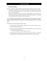
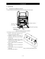
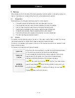
Connections on the rear of the control unit
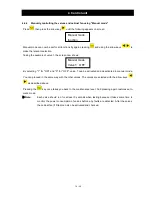
4.2
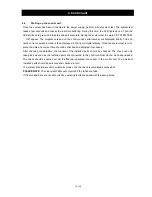
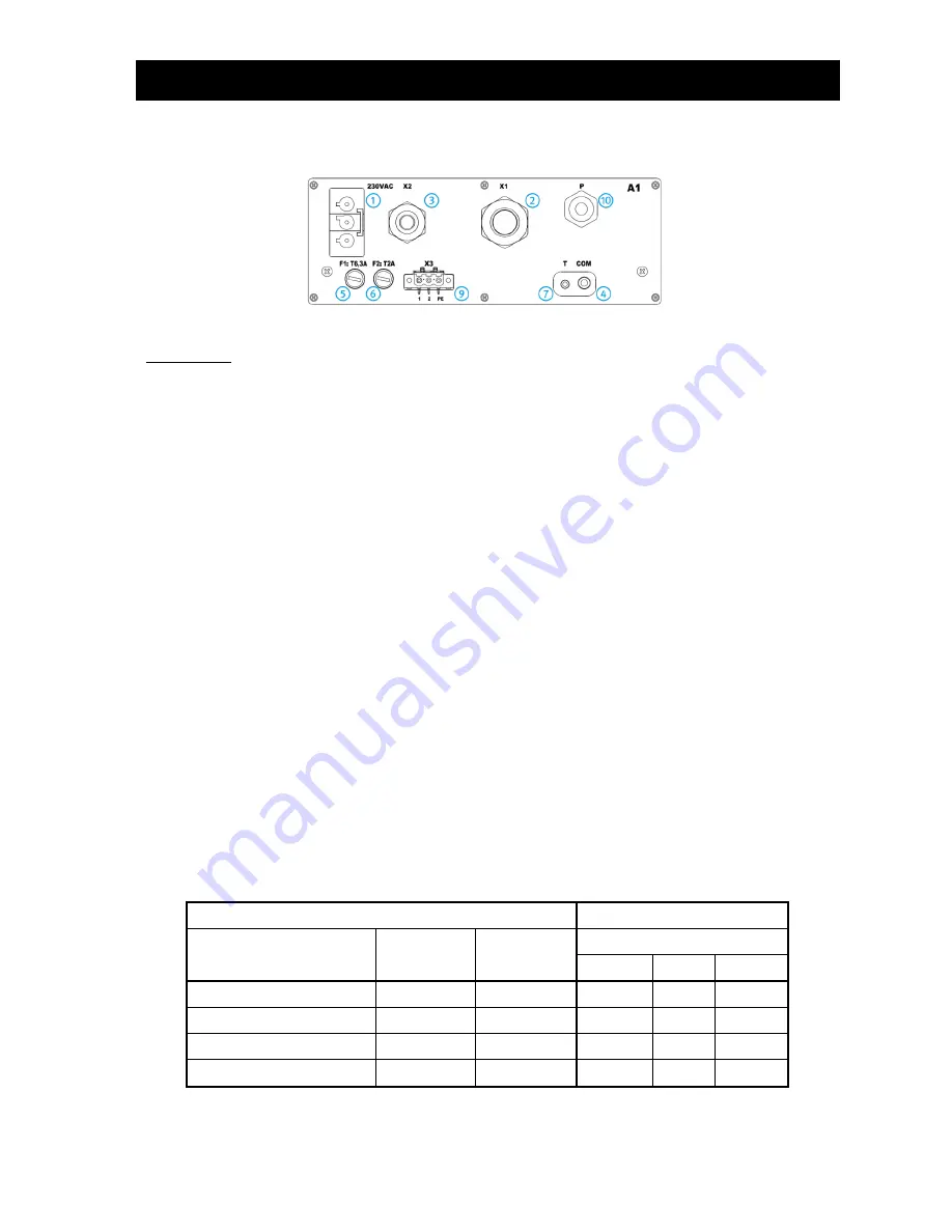
Figure 5: Rear of KL24plus control unit
Connections:
1
Connection for mains cable
230 V AC ~ 50 Hz
2
X1: Pre-assembled valve cable
3
X2: two pin plugs for the air compressor connection
4
COM: Connection for communication module (optional) and/or port for PC
5
F1: T6.3A main fuse, slow blow
6
F2: T2A fuse for UV module, slow blow
7
Connection for temperature sensor, "must be plugged in!"
9
X3: Connection for UV module
10 P: Connection for pressure measuring hose
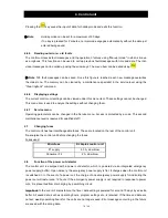
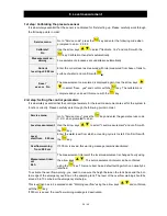
Connections on the air distributor/valve block
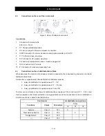
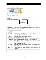
4.3
When delivered, the control unit is already correctly connected to the corresponding connection on the air
distributor/valve block.
A distinction is made between three different air distributor variants:
1. 4-
way air distributor (4 separate valves Y1 …Y4)
2. 3-
way air distributor (3 separate valves Y2 …Y4) and
3. 2-way air distributor (2 separate valves Y3 and Y4)
To allow you to correctly connect up at a later date, the connectors of the control unit (X1.1 …X1.4), their
function (aeration, clear water extraction or sludge extraction) and the connections on the air distributor in
a matrix are shown in detail in the table below.
Control unit
Air distributor connections
Functions
Valves
Connectors
3-way
Y2
Y3
Y4
Aeration
Valve 1
X1.1
X
Clear water extraction
Valve 2
X1.2
X
Sludge Return
Valve 3
X1.3
X
-----
Valve 4
X1.4


