8
/
1
6
5.
Installation and assembly
5.
3
Construction site
Under all circumstances, the following points must be clarified prior to installation:
The structural suitability of the ground
Maximum groundwater levels which occur and drainage capability of the subsoil
Types of load which occur, e.g. traffic loads
An expert ground report should be requested from the local planning authority to determine the physical
characteristics of the subsoil.
5.1 Baffle assembly
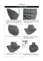
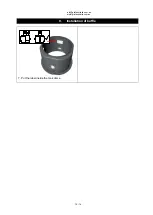
Please refer to the Installation instructions for GRAF baffle
in section 7 of this manual.
5.
2
Tank assembly
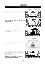
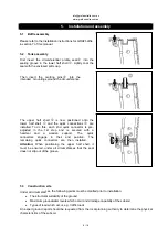
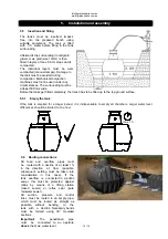
First insert the circumferential profile seal
into the
sealing groove in the lower half shell
. Lightly coat the
seal with the enclosed soft soap.
Then insert the centring pins
into the
intended mountings around the circumference.
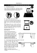
The upper half shell
is now positioned onto the
lower half shell
and the quick connections
are
installed. To do this, each 2nd quick connector is pre-
adjusted in the 1st step and is secured with a
hammer and a wooden support. The quick
connectors engage in their end position. The
remaining quick connectors are then installed.
Attention:
When positioning the upper half shell, it
must be ensured, under all circumstances that the seal
does not slip out of the groove.
info
@graf
australia.com.au
www.graf
australia.com.au


