Filling The Master Divider Valve
Refer to Figure 25 when performing this proce dure:
Verify that all port plugs or performance indica tors have
1.
been removed from all indicator ports in the master
divider valve.
Verify that the system pump is properly con nected to the
2.
inlet port of the master divider valve.
Cycle the system pump sufficiently to fill the main feeder
3.
line between the pump and the master divider valve, and
lubricant is observed being discharged from all of the
indicator ports on the front of the master divider valve
with no evidence of included air.
Reinstall the master divider valve port plugs or
4.
performance indicators into their respective positions.
NOTE
: If any maintenance procedures requiring loosening
or disconnecting of any connec tors or fittings are performed
subsequent to completion of the prefilling procedures described
above, but prior to machine start-up, the prefilling procedures
should be repeated to assure that the lubrication system is
completely filled with lubricant and is air-free. Since the most
critical operating period for a newly installed machine, in terms
of potential for being damaged by unremoved/unfiltered lubri cant
contaminants and lack of adequate lubrication, is the initial start-
up and opera tion, compliance with the recommended prefilling
procedures is crucial for attaining a problem-free start-up of the
machine tool and continued reliable long term operating capability.
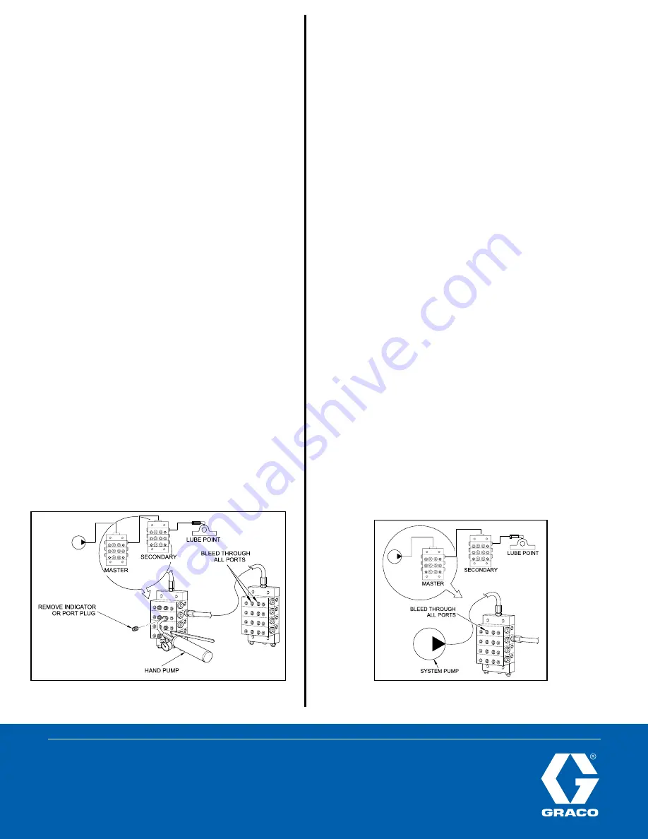
Filling Master-to-Secondary Lube Lines
Refer to Figure 24 when performing this proce dure:
Remove the port plugs or performance indica tors from
1.
all of the indicator ports on the front of the master divider
valve.
Connect a hand pump filled with clean, filtered lubricant
2.
to the indicator port closest to the lube output port that is
feeding the line to the secondary divider valve.
Stroke the hand pump to fill the line between the master
3.
divider valve and secondary divider valve.
Continue to stroke the pump until the lubricant purges all
4.
of the air out of the internal pas sages of the secondary
divider valve and lubri cant flows freely from all indicator
ports with no evidence of included air.
Reinstall the port plugs or performance indica tors in their
5.
respective positions in the second ary divider valve. Do not
replace the port plugs or performance indicators in the
master divider valve yet.
Repeat Steps 1 through 5 for each of the other lube lines
6.
between the master divider valve and all other secondary
divider valves.
Do not replace any of the performance indica tors and port
7.
plugs removed in Step 1 from the master divider valve
assembly until the air-purging procedure described in
Filling the Master Divider Valve has also been completed.
Figure 24
Figure 25
All written and visual data contained in this document are based on the latest product information available at the time of publication. Graco reserves the right to make changes at any time without notice.
Contact us today!
To receive product information or talk with a Graco representative,
call
800-533-9655
or visit us online at
www.graco.com.
©2006-2009 Graco Inc. Form No. L40000 Rev. B 3/09 Printed in U.S.A. All other brand names or marks are used for identification purposes and are trademarks of their respective owners. All written and
visual data contained in this document are based on the latest product information available at the time of publication. Graco reserves the right to make changes at any time without notice.


