background image


Operating Instruction 

Spindle lifting system SL/SM 13xx with SCT iSMPS


Document no : B-00361 

Edition 2020 06


Operating instruction EN 

Copyright by Ergoswiss AG


1/27 


Operating instruction 

 Spindle lifting system SL/SM 13xx with SCT iSMPS 


It is essential to read this operating instruction thoroughly before commissioning the system. 


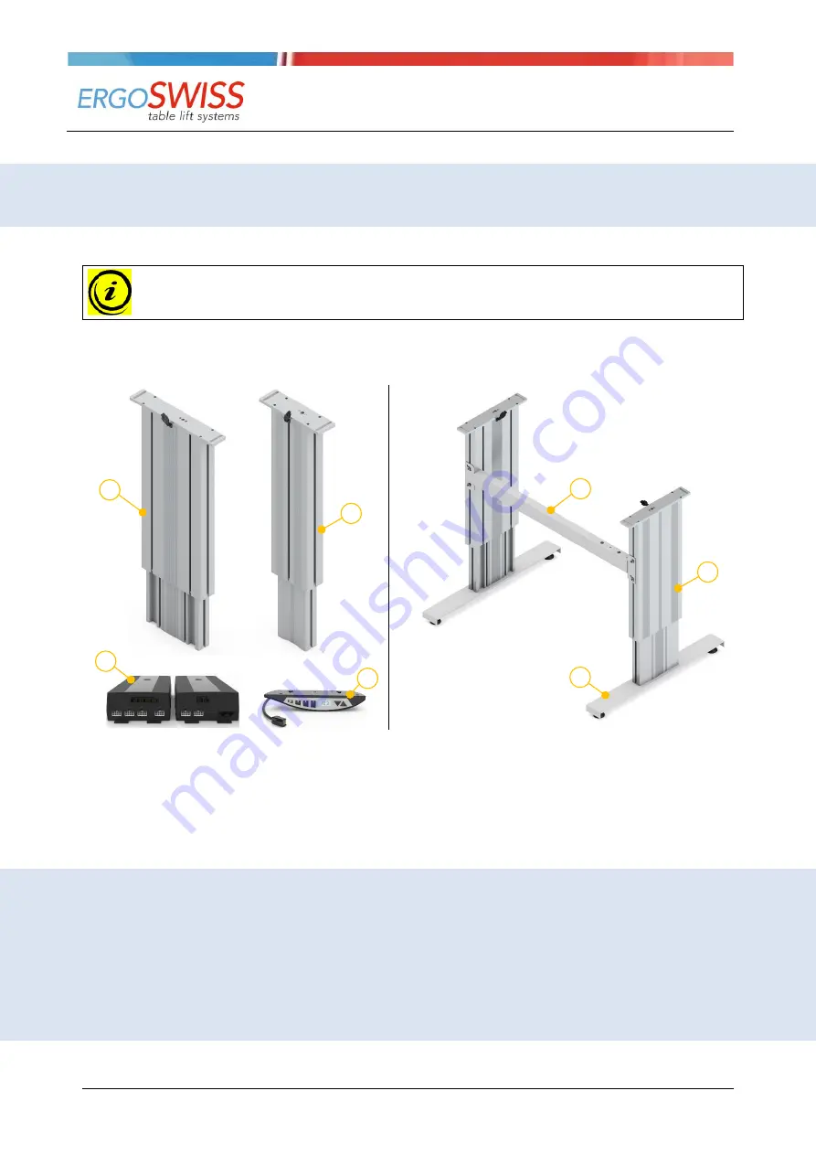
 Spindle lifting column type SL 13xx 

 Spindle lifting column type SM 13xx  

 Control box SCT iSMPS 

 Manual control switch Up-Down or Memory 

Example of a table frame with two lifting columns 
 

 Cross bar 


 Table feet 


Errors and technical changes reserved.  

Ergoswiss AG does not assume any liability for operat-
ing errors or using the products outside of the intended 
purpose use. 
At the time of delivery Ergoswiss AG will replace or re-
pair defect products within accordance with the warranty 
provisions. In addition, Ergoswiss assumes no other lia-
bility. 

For your questions and special custom demand          
Ergoswiss AG will be at your disposal. 


Ergoswiss AG 

Nöllenstrasse 15 
CH-9443 Widnau 
Tel.: +41 (0) 71 727 06 70 
Fax: +41 (0) 71 727 06 79 
 
[email protected] 
www.ergoswiss.com 


Summary of Contents for 901.41017

Page 1: ...Up Down or Memory Example of a table frame with two lifting columns Cross bar Table feet Errors and technical changes reserved Ergoswiss AG does not assume any liability for operat ing errors or using the products outside of the intended purpose use At the time of delivery Ergoswiss AG will replace or re pair defect products within accordance with the warranty provisions In addition Ergoswiss assu...

Page 2: ...g columns 1 2 3 4 1340 Spindle pitch in mm 3 mm 1340 Stroke length in cm 30 cm 40 cm 960 1610 Distance between lifting columns Telescopic cross bar EU Power cable EU CH US 12 11 Manual control switch Up Down 12 Memory 11 12 Other versions Description ESD Electrostatic discharge from external profile via inner profile s01 s99 Special version adapter plate table foot fitting length color etc Notes o...

Page 3: ... Duty cycle monitoring ED 14 5 Operation with the hand switch type Memory 15 5 1 Up Down 15 5 2 Saving and approaching a memory position 15 5 3 Limit the stroke length 16 5 3 1 Limit lower end position Container Stop 16 5 3 2 Limit upper end position Shelf Stop 16 5 4 Locking the movement child protection 17 5 5 Changing the measurement unit mm inch 17 5 6 Setting the shown height on the display 1...

Page 4: ...tions of the symbols and notes Please pay attention to the following explanations of the symbols and notes They are classified according to ISO 3864 2 DANGER Indicates an immediate threatening danger Non compliance with this information can result in death or serious personal injuries invalidity WARNING Indicates a possible dangerous situation Non compliance with this information can result in dea...

Page 5: ...control box SCT4 iSMPS and be operated synchronously The high performance control box SCT4 iSMPS is equipped with two or four motor channels which are ad justed synchronously by an encoder converter Due to the optimised driving comfort the end positions are gently approached as low speed zones up to the standstill An integrated tilt sensor reacts to the system tip ping and can prevent potentially ...

Page 6: ...ties Unless they are supervised by a person responsible for their security or receive instructions by this very person on how to use the device When installing and operating the lifting system the intended purpose of the entire system must be adhered to Commissioning is prohibited until the entire plant complies with the provisions of EG Machinery Directives 2006 42 EG Machinery Directive For this...

Page 7: ...Weight SL 1330 10 8 kg 23 8 lbs SL 1340 11 5 kg 25 4 lbs SM 1330 7 5 kg 16 5 lbs SM 1340 9 3 kg 20 5 lbs Max allowed pressure load 3000 N 674 lbf Max allowed tensile load FTensile stat 500 N 112 lbf FTensile dyn 50 N 11 lbf Power consumption Voltage 24 V Lifting speed Noise level 60 dBA Protection class DIN EN 60529 IP 30 Electrical connection Molex MiniFit plug 8 Pin Cable length 1800 mm 70 8 End...

Page 8: ...yn 150 Nm 110 lbf ft Mbx force x stroke Mby force x stroke Mbx force x stroke Mby force x stroke dyn during the lifting movement 2 4 2 Control box SCT2 iSMPS and SCT4 iSMPS Dimension L B H 309 x 120 x 55 mm 12 2 x 4 7 x 2 2 Weight 1 1 kg 2 4 lbs Supply voltage EU 207 254 4 V 50 Hz 4 5 A US 103 5 127 2 V 60 Hz 7 4 A Primary standby power 0 6 W Power 580 VA Protection class DIN EN 60529 IP 20 Perfor...

Page 9: ...00 12 1330 2x SCT4 iSMPS 400 16 1340 2x SCT4 iSMPS 6 1200 2645 300 12 1330 2x SCT4 iSMPS 400 16 1340 2x SCT4 iSMPS 7 1300 2865 300 12 1330 2x SCT4 iSMPS 400 16 1340 2x SCT4 iSMPS 8 1500 3300 300 12 1330 2x SCT4 iSMPS 400 16 1340 2x SCT4 iSMPS spindle column SL or SM Duty cycle 2 40 operating max 2 min pause 40 min NOTE The lifting system can be subjected to uneven loads as long the max load on the...

Page 10: ...ust be mounted in such a way that driving to the lowest position is pos sible at any time Otherwise no initial operating and reset of the system can be carried out Fixing at the top Adapter plate with long hole screw size M8 Motor cable 1800 mm 70 8 can be extended up to 6000 mm 236 e g 4 motor extension cables of 1500 mm 59 Attachment to T slot cross bar External profile with T slots Fixing botto...

Page 11: ...8x Through hole For screw size M6 Ø5 3 Torque max 6 Nm 4 4 lbf ft Screw in depth mind 15 mm 0 6 4x M6x20 self tapping screw included in the scope of delivery Lifting column type SM Adapter plate top 2x long hole For screw size M8 Inner profile bottom 4x Through hole For screw size M6 Torque max 6 Nm 4 4 lbf ft Screw in depth mind 15 mm 0 6 4x M6x20 self tapping screw included in the scope of deliv...

Page 12: ...w the tabletop Mounting the control box at the bottom of a tabletop 1 Place the control box to the desired lo cation and mark the drill holes with a pen 2 Pre drill three holes Ø 2 5 mm 0 1 Be careful not to drill through the tab letop 3 Fix the control box with three screws torque max 2 Nm 1 5 lbf ft 4 Connect the motor cables to the control box in the order from 1 to 4 Automatic plug detection o...

Page 13: ... 00290 3 3 1 Cable remote control SCT Memory T6 1 Position the hand switch at the desired location underneath the tabletop The control panel must overhang below the work surface 2 Fix the hand switch by using the mounting screws Be careful not to drill through the tabletop 3 3 2 Cable remote control SCT up down 1 Position the hand switch at the desired location underneath the tabletop The control ...

Page 14: ... 1 Keep the buttons and pressed simultaneously to drive to the under block position The system moves downwards at half speed Upward movement is disabled 2 After reaching the block position let go of the buttons and The control box will give a signal sound and the system will drive out a few millimeters After the drive out control box will give another two signal sounds After reaching the block pos...

Page 15: ...5 2 Saving and approaching a memory position With this function it is possible to memorise a certain position height and approach it later by pushing one button With the three memory buttons up to three different positions can be stored and approached 1 Drive to the desired position and press the button M 3 times 2 Press one of the buttons 1 2 3 within 5 s After saving there is a signal sound The ...

Page 16: ...lection S05 with the button M The display stops blinking 4 Press the button or to drive to the desired Container Stop position 5 Confirm with the button M The display shows S05 6 Press the button 1 2 or 3 to leave the menu mode To delete a set Container stop position a new one has to be done with the same procedure 5 3 2 Limit upper end position Shelf Stop To define a Shelf Stop position proceed a...

Page 17: ...ymore and can be operated normally 5 5 Changing the measurement unit mm inch 1 Keep the buttons 1 2 and pressed simultaneously for 4 s The display shows S01 while the S is blinking 2 Press the button or until S07 is selected 3 Confirm the selection S07 with the button M The display blinks cm or inch 4 Press the button or to select the desired measurement unit 5 Confirm with the button M 6 Press th...

Page 18: ...itions are lost 1 If possible Drive to lowest end position This saves time because the system only drives with half speed when doing a reset 2 If needed the system can now be rewired a Remove the cable from the mains b Rewire the system More lifting columns synchronization cables or safety strips can now be connected c Connect the power cable to the mains 3 Keep the buttons 1 2 and pressed simulta...

Page 19: ...lifting element can be loaded with a maximum of 150 kg 330 lbs NOTE During a reset the lifting element retracts completely and the end position reference posi tion of the lifting element is redefined NOTE During the initial operation the lifting element drives with half the speed 1 If possible Drive to lowest end position This saves time because the system only drives with half speed when doing a ...

Page 20: ...to a collision the inclination sensor can be triggered by different causes There fore the following should be observed 1 Install control rigidly before initial commissioning or reset So that the inclination of 0 is properly initialized 2 After the system is moved the inclination sensor should be reinitialized reset according to chapter 5 8 3 For mobile applications e g table on rollers the inclina...

Page 21: ... the reference will be stored at a wrong height This would lead to a collision when driving up to the mechanical block ATTENTION The system can be fully loaded after the initial operation has been completed During initial operation the lifting element can be loaded with a maximum of 150 kg 330 lbs NOTE During a reset the lifting element retracts completely and the end position reference posi tion ...

Page 22: ...les must be ex tended 7 1 Commissioning Initial operation of 2 control boxes Changing from 1 control box to 2 control boxes 1 Connect all cables to the control box accord ing to chapter 3 2 until step 4 2 Connect the SYNC 2 cable to the two control boxes 3 Connect the hand switch to one of the control boxes 4 Connect the power cable to the control box 5 Connect the power cable to the mains 6 Do an...

Page 23: ... Electrical properties Terminal resistance 2 2 kOhm Max switching capacity 250 mW Max Voltage DC 24 V Current min max 1 mA 10 mA 8 1 Commissioning Gluing the contact tube in the squeeze zone 1 Clean and degrease the contact face 2 Pull off a liner of acrylic foam of 10 to 15 cm 3 Place it on the contact face and press on well 4 Repeat steps 2 and 3 until the contact tube is completely glued on 5 M...

Page 24: ...arts may be used For all repair work the system must always be unloaded and voltage free ATTENTION In no case may the control box be opened There is the risk of an electrical shock 9 3 Disassembly and disposal When decommissioning and disposing of the lifting system the electronic parts must be disposed of sepa rately The system consists of components that can be fully recycled and thus they are q...

Page 25: ...n the opposite direction 2 Reset see chapter 5 8 E 65 Movement blocked child lock See chapter 5 4 E 66 Safety strip was triggered Remove jammed object E 69 Safety strip missing Connect or replace the safety strip E 6F Lifting movement monitoring System overloaded remove load from system System jammed remove jammed object Motor not connected correctly connect motor ca ble E 71 Hall sensor wrong mot...

Page 26: ...r defec tive Contact technical support E DB User has set limits incorrectly Contact technical support E DC Control box must be restored to fac tory settings Reset to factory settings see chapter 5 7 E DD Control box must reset Reset see chapter 5 8 10 2 Trouble shooting ATTENTION The lifting system must not be opened reworked or operated by impermissible components Error Cause Rectification Drive ...

Page 27: ...Operating Instruction Spindle lifting system SL SM 13xx with SCT iSMPS Document no B 00361 Edition 2020 06 Operating instruction EN Copyright by Ergoswiss AG 27 27 11 Declaration of Incorporation ...

Reviews: