


TABLE OF CONTENTS
Terms
3
. . . . . . . . . . . . . . . . . . . . . . . . . . . . . . . . . . . . . . . .
How The Electrostatic Air-Assisted Airless
Spray Gun Works
3
. . . . . . . . . . . . . . . . . . . . . . . . . . .
Safety Warnings
4, 5
. . . . . . . . . . . . . . . . . . . . . . . . . . . .
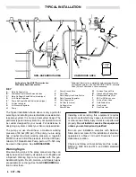
Installation
Typical Installation
6
. . . . . . . . . . . . . . . . . . . . . . . . . . . . . .
Warning Signs
6
. . . . . . . . . . . . . . . . . . . . . . . . . . . . . . . . .
Ventilate the Spray Booth
7
. . . . . . . . . . . . . . . . . . . . . . .
Connect the Air Line
7
. . . . . . . . . . . . . . . . . . . . . . . . . . . .
Check the Electrical Grounding
7
. . . . . . . . . . . . . . . . . .
Connect the Fluid Line
8
. . . . . . . . . . . . . . . . . . . . . . . . . .
Operation
Filter the Fluid
8
. . . . . . . . . . . . . . . . . . . . . . . . . . . . . . . . .
Spraying Operation
8
. . . . . . . . . . . . . . . . . . . . . . . . . . . . .
Operating Checklist
8
. . . . . . . . . . . . . . . . . . . . . . . . . . . . .
Install the Spray Tip and Air Cap
9
. . . . . . . . . . . . . . . . .
Adjust the Spray Pattern
9
. . . . . . . . . . . . . . . . . . . . . . . .
Maintenance
Daily Care and Cleaning
10
. . . . . . . . . . . . . . . . . . . . . . .
Flush the Spray Gun
10
. . . . . . . . . . . . . . . . . . . . . . . . . . .
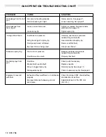
Spray Pattern Troubleshooting Chart
11
. . . . . . . . . .
Gun Operation Troubleshooting Chart
12
. . . . . . . . .
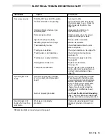
Electrical Troubleshooting Chart
13
. . . . . . . . . . . . . .
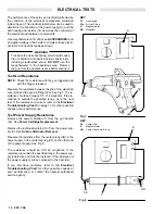
Electrical Tests
Test Gun Resistance
14
. . . . . . . . . . . . . . . . . . . . . . . . . . .
Test Power Supply Resistance
14
. . . . . . . . . . . . . . . . . .
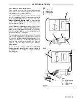
Test Resistor Stud Resistance
15
. . . . . . . . . . . . . . . . . .
Service
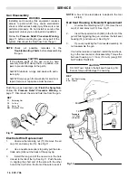
Gun Disassembly
16
. . . . . . . . . . . . . . . . . . . . . . . . . . . . .
Electrode Wire Replacement
16
. . . . . . . . . . . . . . . . . . . .
Ball Seat Housing & Resistor Replacement
16
. . . . . . .
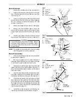
Barrel Removal
17
. . . . . . . . . . . . . . . . . . . . . . . . . . . . . . .
Barrel Reassembly
17
. . . . . . . . . . . . . . . . . . . . . . . . . . . .
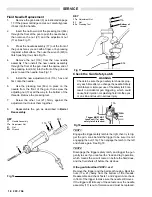
Fluid Needle Replacement
18
. . . . . . . . . . . . . . . . . . . . .
Check the Gun Safety Latch
18
. . . . . . . . . . . . . . . . . . . .
Power Cartridge Replacement
19
. . . . . . . . . . . . . . . . . .
Turbine Alternator Removal
20
. . . . . . . . . . . . . . . . . . . . .
Fan Air Valve Replacement
21
. . . . . . . . . . . . . . . . . . . . .
Air Valve Replacement
21
. . . . . . . . . . . . . . . . . . . . . . . . .
ES ON-OFF Valve Removal and Repair
22
. . . . . . . . . .
Muffler, Check Valve & Inlet Filter Replacement
22
. . .
Repair Kits
23
. . . . . . . . . . . . . . . . . . . . . . . . . . . . . . . . . .
Parts Drawing
24
. . . . . . . . . . . . . . . . . . . . . . . . . . . . . . . .
Parts List
25
. . . . . . . . . . . . . . . . . . . . . . . . . . . . . . . . . . . .
Accessories
26–28
. . . . . . . . . . . . . . . . . . . . . . . . . . . . . .
Technical Data
29
. . . . . . . . . . . . . . . . . . . . . . . . . . . . . . .
Graco Phone Numbers
29
. . . . . . . . . . . . . . . . . . . . . . .
Spray Tip Selection Chart
30, 31
. . . . . . . . . . . . . . . . . .
Warranty
Back Cover
. . . . . . . . . . . . . . . . . . . . . . . . . . . .
TERMS
WARNING: Alerts user to avoid or correct conditions that could
cause bodily harm.
CAUTION: Alerts user to avoid or correct conditions that could
cause damage to or destruction of equipment.
NOTE: Identifies essential procedures or helpful information.
FLUID INJECTION INJURY: A serious injury, which may ap-
pear to be a simple cut, caused by high pressure injection of
fluid directly into the body.
PRESSURE RELIEF PROCEDURE: A safety procedure for
relieving air and fluid pressure in the system.
FOR YOUR SAFETY: Alerts user to read the additional safety
warnings on the page indicated.
ES ON-OFF VALVE: An on/off switch located near the rear of
the gun, above the gun handle, that turns the electrostatic pow-
er on or off.
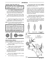
HOW THE ELECTROSTATIC AIR-ASSISTED AIRLESS SPRAY GUN WORKS
This gun combines electrostatic air spray and airless
spraying concepts. The air has three functions: (1) to
drive the turbine, (2) to help atomize the paint “tails”, and
(3) to help control the pattern size.
The turbine generates power that the power cartridge
converts to a high voltage current. The high voltage cur-
rent charges the gun’s ionizing electrode.
Fluid is electrostatically charged as it passes the gun’s
ionizing electrode. The charged fluid is attracted to the
grounded work piece, wrapping around and evenly coat-
ing all surfaces.
The spray tip shapes the fluid into a fan pattern, similar to
a conventional airless spray tip, but at a lower pressure.
Air from the air cap further atomizes the fluid and pushes
the paint tails into the pattern. The fan adjusting knob
controls the width of the pattern.
Note that the air-assisted airless spray gun differs from
the conventional air spray gun in that increasing the fan
air reduces the pattern width. To increase the pattern
width, less fan air or a larger size tip must be used.
Содержание PRO AA4000
Страница 2: ... ...


