308986
11
Installation
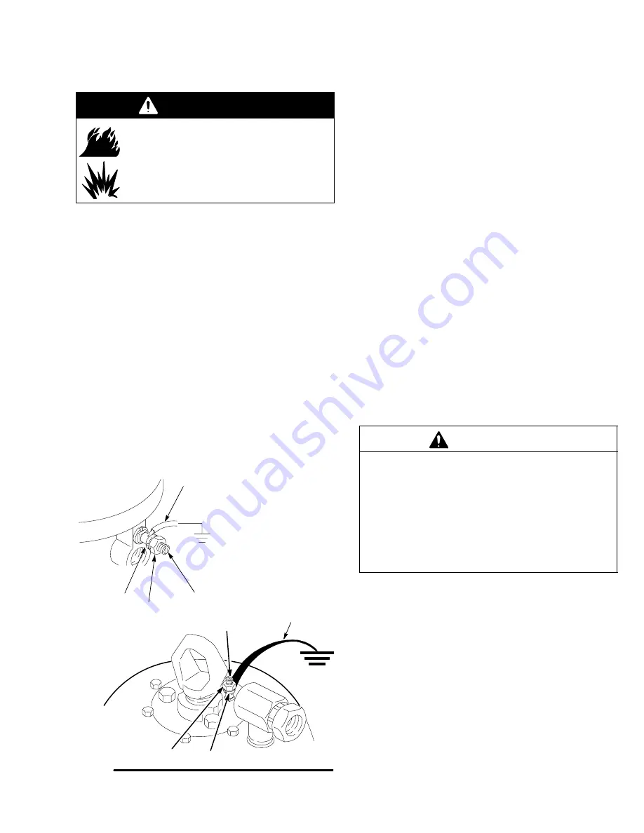
Grounding
WARNING
FIRE AND EXPLOSION HAZARD
Improper grounding could cause static
sparking, which could cause a fire or
explosion. To reduce the risk of property
damage or serious injury, follow the
grounding instructions below.
The following grounding instructions are minimum
requirements for a system. Your system may include
other equipment or objects which must be grounded.
Check your local electrical code for detailed grounding
instructions for your area and type of equipment. Your
system must be connected to a true earth ground.
1.
Pump:
a.
Loosen the grounding lug locknut (Fig. 4,
Item BB) and washer (AA).
b.
Insert one end of a 14 ga. (1.5 mm
@
) minimum
ground wire (G) into the slot in lug (CC) and
tighten the locknut securely.
c.
Connect the other end of the ground wire to a
true earth ground.
Fig. 4
G
BB
AA
CC
G
BB
AA
CC
Select you application
Available Accessories (must be
purchased separately)
1.
Air hoses:
use only grounded hoses with a maxi-
mum of 500 feet (150 m) combined hose length to
ensure grounding continuity.
2.
Air and Paint Line Filters:
locate all filters and
learn all filter cleaning procedures before operating
the system. Optional filters are available to meet
particular system needs. Be sure all filters are
checked and cleaned every day.
3.
Filters:
be sure your hydraulic power supply (U) is
equipped with a suction filter to the hydraulic pump
and a system return line filter (S) of 10 micron size.
Carefully follow the manufacturer’s recommendations
on reservoir and filter cleaning, and periodic changes
of hydraulic fluid. Use only Graco approved hydraulic
oil. Order Part No. 169–236, 5 gallon (19 liter) or
207–428, 1 gallon (3.8 liter).
4.
Hydraulic Line Accessories:
on the hydraulic
supply line (Item C, Fig. 3), install the following
accessories in the order shown in Fig. 3, using
adapters as necessary.
CAUTION
It is very important to keep the hydraulic supply
system clean at all times. Be sure that all hydraulic
fluid lines are absolutely clean. Blow out the lines
with air and flush thoroughly with solvent before
connecting to the hydraulic motor, to avoid introduc-
ing harmful contaminants into the motor.
For optimum pump performance, keep the tempera-
ture of the hydraulic oil below 130
_
F (54
_
C).
a.
Shutoff valve (P): to isolate the pump for
servicing.
b.
Fluid pressure gauge (F):
to monitor hydraulic
oil pressure to the motor and to avoid over-
pressurizing the motor or displacement pumps.
c.
Pressure and temperature-compensated flow
control valve (G): to prevent the motor from
running too fast and possibly damaging itself.
d.
Pressure reducing valve (H) with drain line (E):
running directly into the hydraulic return
line (D).
e.
Accumulator (J): to reduce the hammering
effect caused by the motor reversing direction.
Содержание HYDRA-CAT FIXED RATIO
Страница 38: ...38 308986 Notes...
Страница 39: ...308986 39 Notes...


