307132
7
Installation
TI0645
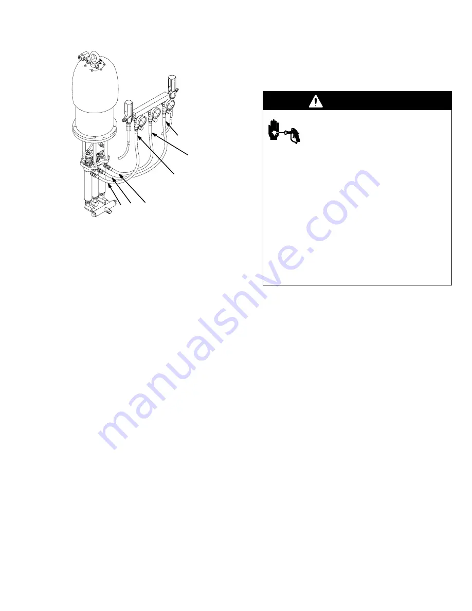
Ensure hoses are routed correctly
during installation with three dis-
placement pump models.
A
A
B
A
A
B
NOTE:
See page 22 for accessories mentioned in this
section.
In the following instructions, the base fluid will always
be called part A and the catalyst will be called part B.
With three displacement pump models, always use the
two outer displacement pumps to supply part A and
the middle displacement pump to supply part B.
Mount pump to suit the type of installation planned.
Accessory wall mounting bracket is shown on page 22,
pump dimensional drawing and mounting hole layout
are shown on page 24. When mounting pump on wall,
be sure the wall is strong enough to support the pump
and other equipment, plus any stress developed when
equipment is operating. Drill three 3/16 in. diameter
holes in mounting bracket as shown on page 24. Using
screws (43 or 56), screw manifold (49 or 62) onto
bracket.
Connect part A inlet hose to 3/4 npt inlet of manifold on
three displacement pump models, or to 3/4 npt inlet of
left hand displacement pump on two displacement
pump models. Connect part B inlet hose to 3/4 npt
swivel union inlet of center displacement pump mod-
els.
System Accessories
Install the accessories in the order shown in the
Typi-
cal installations
on pages 5 and 6. Working up-
stream from the pump inlet, install a pump runaway
valve (B) to shut off the air to the pump if the pump
accelerates beyond the pre-adjusted setting. A pump
which runs too fast can be seriously damaged.
Next, install an air line lubricator (C) for automatic air
motor lubrication, a bleed-type master air valve (A) to
relieve air trapped between the valve and the pump, an
air regulator (D) to control pump speed, and an air filter
(E) to remove harmful dirt and moisture from the com-
pressed air supply.
Install a fluid drain valve (G) at each fluid outlet to re-
lieve pressure in the system. Be sure the valve is
pointed downward.
WARNING
INJECTION HAZARD
Two accessories, the bleed-type master
air valve (A) and the fluid drain valve (G)
are required for your system to reduce
the risk of serious injury from moving parts, fluid
injection, or splashing when shutting off the pump.
The bleed-type air valve relieves air trapped be-
tween the valve and the pump, after the pump is
shut off. Trapped air can cause the pump to cycle
unexpectedly and result in serious injury if you are
adjusting or repairing the pump.
The fluid drain valve helps relieve fluid pressure in
the displacement pump, hose and gun when shut-
ting off the pump. Triggering the gun to relieve
pressure may not be sufficient, especially if there is
a clog in the hose, gun/dispensing valve, or tip/
nozzle.
Install and connect feed pumps, solvent pump, mixer,
etc. See
Typical installations
on pages 5 and 6
and separate component instructions.
Feed Systems
Material supply must be pressure fed into each propor-
tioning cylinder. If materials require heating they can
be heated in the supply feed as well as the outbound
side of the pumps. Material supply is critical to proper
proportioner operation. Material must fill the proportion-
er cylinders on their upstroke totally to elimiate a “div-
ing” of the cylinders on the top change–over. This “div-
ing” will also be seen as a pressure drop at the change
over. This will cause an off ratio condition.
Ensure your feed systems are designed to supply
twice the volume used by each componet. This supply
pump pressure should never exceed 25% of the pro-
protioner output pressure.
Example:
4:1 proportioner. 2.0 gpm output, 1000 psi.
4:1 ratio at 2.0 gpm = 1.5gpm of “A” component and
1/2 (.5) gpm of component “B”.
“A” feed pump needs to have a 4 gpm capacity
at a max of 250psi.
B" feed pump needs to be at least 1 gpm at
250 psi max.
Review your feed systems with your Graco Distributor.
Содержание BULLDOG HYDRA-CAT 208958
Страница 17: ...307132 17 Notes...
Страница 23: ...307132 23 Notes...


