background image

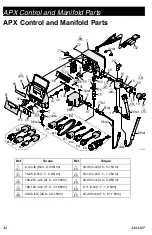
APX Control and Manifold Parts

3A4442F

43

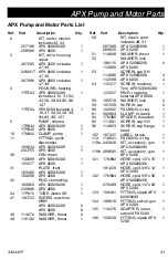
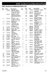
APX Control and Manifold Parts List

Ref.

Part

Description

Qty.

7

17R029

BOARD, control 

(APX 6200/8200) 

includes 25, 28, 40, 

63, 65, 72, 76,82

1

17S871

BOARD, control 

(APX 5200) 

includes 

25, 28, 40, 63, 65, 72, 

82

1

9

17R757

COVER, control 

includes 41, 46, 67, 

68, 69, 77, 87, 116

1

12

17N678

MANIFOLD, 

transducer

1

13

243222

TRANSDUCER, 

pressure control 

includes 21

1

14

117556

FITTING, nipple

1

15

193710

SEAL, seat, valve

1

16

193709

SEAT, valve

1

17

287879

ASSEMBLY, valve, 

drain

1

18

114708

SPRING, 

compression

1

19

15G563

HANDLE, valve

1

20

116424

NUT, cap

1

21

111457

PACKING, o-ring

1

22

15J002

FITTING, elbow, 45°

1

25

16U013

SCREW, machine, 

HWH

3

28

118444

SCREW, machine, 

HWH

1

41

16V095

SCREW, machine

4

42

256219

POTENTIOMETER

1

43

15C973

GASKET

1

44

116167

KNOB, potentiometer

1

45

15D527

SWITCH, rocker, 

240V (APX 

6200/8200)

1

15C979

SWITCH, rocker, 

120V (APX 5200)

1

46

16Y788

LABEL, blank

1

63

121889

O-ring

1

64

CORD, power

64a

16M836

APX 6200, Multicord, 

Model 17N343, 

17N347

1

64b

16M834

APX 6200, CEE 7/7

Model 17N345

1

64c

15G938

APX 8200, 

Models 17N350, 

17N354

1

64d

15G957

APX 8200, CEE 7/7 

Model 17N352

1

64e

17A242

CORDSET, adapter, 

Australia

1

64f

15D530

APX 5200, U.K.

1

65

253103

Italy/Denmark/

Switzerland

1

66

114391

SCREW, grounding

2

67

16X796

LABEL, 

SmartControl3.0

1

68

16Y496

BOARD, display, 

LED 

includes 70

1

69

16X797

LABEL, 

SmartControl3.0, 

ProGuard

1

70

115522

SCREW, machine

3

71

BOARD, filter 

24R597

APX 5200

1

24R598

APX 6200

1

24U823

APX 8200

1

72

119228

SCREW, machine

2

73

126029

SWITCH, rocker 

(APX 6200/8200)

1

120059

SWITCH, rocker 

(APX 5200)

1

74

15G935

CONNECTOR, 

electrical

1

75

117745

BUSHING, strain 

relief (APX 

6200/8200)

1

76

16T544

ADAPTER, cord 

(APX 6200/8200)

1

16T546

ADAPTER, cord 

(APX 5200)

1

77

117625

NUT, locking (APX 

6200/8200)

2

87

260067

FITTING, strain relief 

(APX 6200/8200)

1

92

17P272

BAR, ground (APX 

6200/8200)

1

116

17P395

LABEL, switch

1

126

121249

LOCK, cord

1

135

24V030

KIT, repair, coil filter, 

APX8200 

includes 

136

1

136

16U215

SCREW, Phillips PH

1

137

121249

RETAINER, plug 

adapter

1

142

17N437

WIRE, jumper (APX 

5200)

1

143

17V290

SUPRESSOR, ferrite 

(APX 5200)

1

Ref.

Part

Description

Qty.

Содержание APX 5200

Страница 1: ...els APX 5200 APX 6200 and APX 8200 See page 2 for model information including maximum working pressure and approvals Important Safety Instructions Read all warnings and instructions in this manual and related manuals Be familiar with the controls and the proper usage of the equipment Save these instructions Related Manuals Gun 309495 APX 6200 8200 Pump 332922 Gun 308491 APX 5200 ti29970a www graco...

Страница 2: ...rol Parts 45 Wiring Diagrams 46 Wiring Diagrams 47 Technical Specifications 48 Graco Standard Warranty 51 Models 3000 psi 20 7MPa 207bar Maximum Working Pressure VAC Model 110 U K APX 5200 17S762 APX 5200 with bag roller 17S769 230 Europe Multi APX 6200 17N343 APX 8200 17N350 APX 6200 with bag roller 17N344 APX 8200 with bag roller 17N351 230 CEE 7 7 APX 6200 17N345 APX 6200 with bag roller 17N346...

Страница 3: ...ck When repair or replacement of the cord or plug is required do not connect the grounding wire to either flat blade terminal The wire with insulation having an outer surface that is green with or without yellow stripes is the grounding wire Check with a qualified electrician or serviceman when the grounding instructions are not completely understood or when in doubt as to whether the product is p...

Страница 4: ...ple do not try to stop leaks with any part of the body Always use the nozzle tip guard Do not spray without nozzle tip guard in place Use Graco nozzle tips Use caution when cleaning and changing nozzle tips In the case where the nozzle tip clogs while spraying follow the Pressure Relief Procedurefor turning off the unit and relieving the pressure before removing the nozzle tip to clean Equipment m...

Страница 5: ...ent is rated and approved for the environment in which you are using it ELECTRIC SHOCK HAZARD This equipment must be grounded Improper grounding setup or usage of the system can cause electric shock Turn off and disconnect power cord before servicing equipment Connect only to grounded electrical outlets Use only 3 wire extension cords Ensure ground prongs are intact on power and extension cords Do...

Страница 6: ...se serious injury or property damage Use only compatible water based solvents to clean plastic structural or pressure containing parts See Technical Specifications in this and all other equipment instruction manuals Read fluid and solvent manufacturer s Safety Data Sheet SDS and recommendations PERSONAL PROTECTIVE EQUIPMENT Wear appropriate protective equipment when in the work area to help preven...

Страница 7: ... OFF Switch C Pressure Control D VIBRA FLO ON OFF Switch 6200 8200 models E VIBRA FLO Control 6200 8200 models F Power Cord G Drain Tube H Prime Spray Valve J Pump K VIBRA FLO Hopper Shaker 6200 8200 models L Amp Switch M Hopper with cover N Hopper Strainer P Trigger Lock R Hose S Bag Roller Optional Model Serial Tag Located on bottom ...

Страница 8: ...d protects the sprayer against high and low voltage spikes If the sprayer is plugged into a power source that goes too low or too high the sprayer stops operating VIBRA FLO Shaker 6200 8200 models The hopper shaker vibrates the hopper which assists in moving the material down to the pump inlet at the bottom of the hopper Bag Roller Optional Bags of material can be difficult to empty A bag roller p...

Страница 9: ...te to mix with mixing paddle to a smooth lump free consistency 3 Make certain all dry powder clumps are mixed throughly before pouring mixture into the sprayer hopper PREMIX 5 GAL ti2493b NOTICE Failure to make certain that all dry powder is throughly mixed may cause tip or pump clogging ti30766a ...

Страница 10: ...il Turn prime valve down Leave prime valve in the down drain position until you are ready to spray again 7 If you suspect the spray tip or hose is clogged or that pressure has not been fully relieved a VERY SLOWLY loosen the tip guard retaining nut or the hose end coupling to relieve pressure gradually b Loosen the nut or coupling completely c Clear hose or tip obstruction This equipment stays pre...

Страница 11: ...Connect whip hose if applicable and gun to other end of hose Apply thread sealant and tighten securely 3 Engage trigger lock 4 Remove tip guard 5 A hopper strainer is used to prevent debris from entering the pump 6 Fill throat packing nut with Graco TSL to preventprematurepacking wear Do this each time you spray 7 Turn ON OFF switch to the OFF position 8 Plug power supply cord into a properly grou...

Страница 12: ...g roller assembly in the lower position On the APX 8200 model position the bag roller assembly in the upper position Place bag roller on top of the sprayer and secure with hardware provided The bag roller length is adjustable to accommodate various material bag lengths Adjust by loosening the two handle screws and sliding the extension in or out Increase bag roller tension by adjusting the tension...

Страница 13: ... pressure control to lowest pressure 3 Turn ON OFF switch to the ON position 4 6200 8200 models Turn VIBRA FLO ON OFF switch to the ON position 5 Increase pressure 1 2 turn to start motor and allow fluid to circulate through drain tube for 15 seconds turn pressure down 6 Turn prime valve horizontal to SPRAY position Disengage trigger lock ti29980a ti29981a ti29982a ti29983a 00 15s 1 2 50 ti29240a ...

Страница 14: ...is in use 3 Turn ON OFF switch to the ON position Turn prime valve down 4 Increase pressure to start pump 5 Install hopper filter by pushing it through the material in the bottom of the hopper until it is in place Open end of the filter should be pointed towards the pump inlet 6 Add remaining material to the hopper 7 Turn VIBRA FLO knob to maximum 8 If the shaker is making excessive noise turn the...

Страница 15: ... Cut open the other end of the bag 6 Turn bag roller handle to push contents into the hopper 7 Turn bag roller handle the opposite direction to remove empty bag from the roller VIBRA FLO Shaker Adjustment 6200 8200 models The hopper shaker speed is adjusted by adjusting the VIBRA FLO knob on the control 1 Turn shaker ON OFF switch to the ON position 2 Turn VIBRA FLO knob to maximum 3 If the shaker...

Страница 16: ...pper shaker is shipped with the gap preset for the best performance If the armature and coil is replaced or needs adjustment use a feeler gauge to adjust shaker gap Set gap to 0 042 0 052 inch 1 06 1 32 mm 1 2 3 4 5 ti30151a ti30152a ti30153a ti30154a ti30155a ...

Страница 17: ...shown a Use spray tip to align gasket and seal in the tip guard b Spray tip must be pushed all the way into the tip guard Turn spray tip to push down c Turn the arrow shaped handle on the spray tip forward to the spray position 4 Screw spray tip and tip guard assembly onto the gun and tighten ti29241a SPRAY TIP RUBBER GASKET METAL SEAL RETAINING NUT TIP GUARD ti29242a ti29243a ti29244a ...

Страница 18: ...en turning to the unclog position perform Pressure Relief Procedure page 10 then turn Prime Spray valve to spray position and repeat step 1 2 Engage trigger lock Rotate spray tip back to spray position Disengage trigger lock and continue spraying SPRAY Useful Tip When spraying if the gun is not used for a significant period of time be sure to clean the sprayer or keep the gun wet by placing in wat...

Страница 19: ...ug sprayer and locate good voltage supply to prevent damage to electronics Typical cause of this error is plugging into a circuit that is higher than the rated voltage of the sprayer Find a circuit that supplies the correct voltage Incoming voltage too low for sprayer operation unplug sprayer and locate good voltage supply to prevent damage to electronics Typical cause of this error is other equip...

Страница 20: ...mode and pressure must be at zero Job Gallons 1 Short press DTS button to move to Job Gallons or liters x 10 2 Press and hold to reset to zero NOTE JOB scrolls past then the number of gallons sprayed above 400 psi 28 bar 2 8 MPa displays Lifetime Gallons 1 Short press DTS button to move to Lifetime Gallons or liters x 10 NOTE LIFE scrolls briefly then the number of gallons sprayed above 400 psi 28...

Страница 21: ...1 displays 4 Short press DTS button and MOTOR HOURS scrolls past and then total motor run hours are displayed 5 Short press DTS button LAST CODE scrolls by and last code is displayed e g E 07 6 Press and hold DTS button to clear code to zero 7 Short press to move to SOFTWARE REV 8 Short press DTS button MOTOR ID RESISTOR scrolls by and model code number see below ti29981a ti22720b Motor ID Number ...

Страница 22: ... Add flushing fluid to the hopper 5 Increase pressure to 1 2 Hold gun against pail Disengage trigger lock Trigger gun until flushing fluid appears 6 Move gun to waste pail hold gun against pail trigger gun to thoroughly flush system Release trigger and engage trigger lock 7 Turn prime valve down to DRAIN position and allow flushing fluid to circulate until flushing fluid appears clear 8 Turn prime...

Страница 23: ...urn ON OFF switch to the OFF position 10 Turn prime valve down DRAIN position Unplug sprayer 11 If flushing with water flush again with Pump Armor to leave a protective coating to prevent freezing or corrosion 12 Wipe sprayer hose and gun with a rag soaked in water ti30010a ti29977a ti30012a ti30013a ...

Страница 24: ...efill and reprime pump Hopper strainer clogged Remove and clean then reinstall Hopper filter is too fine Remove filter or replace with a larger mesh filter Intake valve ball and piston ball are not seating properly Remove intake valve and clean Check balls and seats for nicks replace if necessary see pump manual Prime valve leaking Relieve pressure Repair prime valve Verify pump does not continue ...

Страница 25: ...Switch to 16A or 20A setting Change to circuit that provides 16A or 20A Change to less loaded circuit Motor runs but pump does not stroke Connecting rod assembly damaged see pump manual Replace connecting rod assembly see pump manual Gears or drive housing damaged Inspect drive housing assembly and gears for damage and replace if necessary see pump manual Excessive material leakage into throat pac...

Страница 26: ... Hopper connections are not tight or elbow o ring is damaged or missing Check hopper connections and tighten as necessary Inspect for o ring Replace o ring if it is damaged No display sprayer operates Display is damaged or has bad connection Check connections Replace display VIBRA FLO shaker does not run No power Make certain sprayer and shaker ON OFF switches are ON Shaker coil is defective Repla...

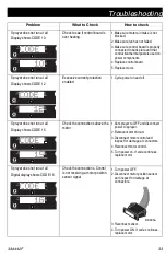
Страница 27: ...sures sprayer is in normal run mode 3 Turn pressure control knob clockwise 1 2 turn 4 View digital display Keep clear of electrical and moving parts during troubleshooting procedures To avoid electrical shock hazards when covers are removed for troubleshooting wait 5 minutes after disconnecting power cord for stored electricity to dissipate Problem What to Check How to check Sprayer does not run a...

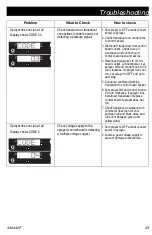
Страница 28: ... 3 Set sprayer to OFF and disconnect power to sprayer 4 Check transducer and connections to control board 5 Disconnect transducer from control board socket Check that transducer and control board contacts are clean and secure 6 Reconnect transducer to control board socket Connect power set sprayer ON and control knob 1 2 turn clockwise If sprayer does not run properly set sprayer to OFF and go to ...

Страница 29: ...n clockwise If sprayer does not run set sprayer to OFF and go to next step 5 Connect a confirmed working transducer to control board socket 6 Set sprayer ON and control knob to 1 2 turn clockwise If sprayer runs install new transducer Replace control board if sprayer does not run 7 Check transducer resistance with ohmmeter less than 9k ohm between red and black wires and 3 6k ohm between green and...

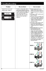
Страница 30: ...connector and control board contacts are clean and secure If contacts are clean and secure continue to step 4 4 Set sprayer to OFF and spin motor fan 1 2 turn Restart sprayer If sprayer runs replace control board If sprayer does not run continue to step 5 5 Perform Spin Test Test at large 4 pin motor field connector Disconnect fluid pump from sprayer Test motor by placing a jumper across pins 1 2 ...

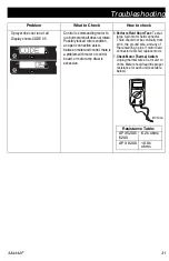
Страница 31: ...tor amp draw is excessive 6 Perform Field Short Test Test at large 4 pin motor field connector There should not be continuity from pin 4 the ground wire and any of the remaining 3 pins If motor field connector tests fail replace motor 7 Check Motor Thermal Switch Unplug thermal wires Set meter to ohms Meter should read the proper resistance for each unit see table below Problem What to Check How t...

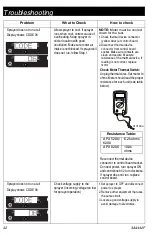
Страница 32: ... If reading is not correct replace motor Check Motor Thermal Switch Unplug thermal wires Set meter to ohms Metershouldreadtheproper resistance for each unit see table below Reconnect thermal device connector to control board socket Connect power turn sprayer ON andcontrolknob1 2turnclockwise If sprayer does not run replace control board Sprayer does not run at all Display shows CODE 08 Check volta...

Страница 33: ...le power on and off Sprayer does not run at all Display shows CODE 15 Check the connections above the motor 1 Set sprayer to OFF and disconnect power to sprayer 2 Remove motor shroud 3 Disconnect motor control and inspect for damage at connectors 4 Reconnect motor control 5 Turn power on If code continues replace motor Sprayer does not run at all Digital display shows CODE 16 Check the connections...

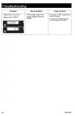
Страница 34: ...run at all Display shows CODE 17 Check voltage supply to the sprayer plugged into wrong voltage 1 Set sprayer to OFF and disconnect power to sprayer 2 Locate a good voltage supply to avoid damage to electronics Problem What to Check How to check ...

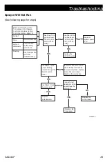
Страница 35: ...100 VAC 220 VAC for 230V units NO See Step 2 Do you have over 100 VAC 220 VAC for 230V units YES NO Repair or replace power cord Replace the ON OFF switch YES See Step 3 Is the proper reading present through the thermal switch wires YES See Step 4 Does the motor run YES Replace potentiometer NO If motor is hot let cool and retest If Step 3 still shows incorrect resistance replace motor The motor h...

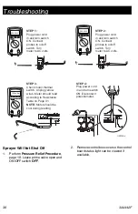
Страница 36: ...240V V 100k ohm ti29216a STEP 1 Plug power cord in and turn switch ON Connect probes to on off switch Turn meter to AC volts STEP 2 Plug power cord in and turn switch ON Connect probes to on off switch Turn meter to AC volts STEP 3 Check motor thermal switch Unplug yellow wires Meter should read according to Resistance Table on Page 31 NOTE Motor should be cool during reading STEP 4 Plug power cor...

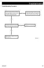
Страница 37: ...witch ON Does sprayer reach or exceed its maximum pressure NO Mechanical problem See the proper fluid pump manual for the sprayer for further trouble shooting procedures YES Unplug the transducer from control board Does motor stop running YES Bad transducer Replace and test with a new one NO Replace the control board ti29218a ...

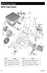
Страница 38: ...t Parts 12 20 22 22 22 22 30 25 25 25 25 21 Ref Torque Ref Torque 70 80 in lb 7 9 9 0 N m 200 230 in lb 22 6 26 N m 25 30 ft lb 33 9 40 1 N m 30 35 in lb 3 4 3 9 N m 22 28 in lb 2 5 3 2 N m 170 190 in lb 19 2 21 5 N m 12 22 20 25 21 30 ...

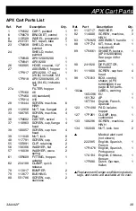
Страница 39: ...HER flat 2 57 116038 WASHER wave spring 2 61 15R609 FITTING hopper adapter 1 62 234188 CLAMP quick release 1 78 113817 BUMPER 2 79 113677 BUSHING 1 80 551786 SCREW cap stainless 2 81 112717 WASHER 2 82 114000 SCREW machine HWH 3 83 17N920 ASSEMBLY handle 1 88 17P774 KIT hose drain includes 90 1 89 17N661 SHAKER texture APX 6200 8200 See page 44 for parts 1 90 241920 DEFLECTOR threaded 1 91 111800 ...

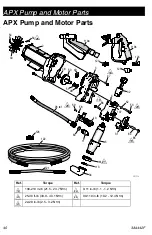
Страница 40: ...5 61 113 34 107 52 53 84 11 60 26 ref 85 31 59 122 126 119a 123 121 58 2 3 30 124 125 10 ti30594b 119b 54 18 26 18 18 20 28 21 Ref Torque Ref Torque 190 210 in lb 21 5 23 7 N m 9 11 in lb 1 1 1 2 N m 25 30 ft lb 33 9 40 1 N m 90 110 in lb 10 2 12 4 N m 22 28 in lb 2 5 3 2 N m 18 26 20 28 21 ...

Страница 41: ...0 6 48 114672 WASHER thrust 2 49 116192 WASHER thrust 1 50 KIT repair gear includes 48 51 287290 APX 5200 6200 1 288035 APX 8200 1 51 114699 WASHER thrust 1 52 WASHER lock 106115 APX 5200 6200 4 112600 APX 8200 53 SCREW cap SH 114666 APX 5200 6200 4 112599 APX 8200 4 54 115477 SCREW machine Torx APX 5200 6200 1 122347 RING retaining external APX 8200 1 58 105510 WASHER lock 2 59 101550 SCREW cap 2...

Страница 42: ... 64e 64f 116 44 42 45 67 69 41 9 98 ref 88 ref 26 ref 20 19 18 17 25 16 15 12 22 142 ti30614b 25 25 26 23 23 24 19 5 27 9 18 20 Ref Torque Ref Torque 2 3 in lb 0 23 0 34 N m 40 45 in lb 4 5 5 1 N m 15 25 in lb 1 7 2 8 N m 10 15 in lb 1 1 1 7 N m 190 210 in lb 21 5 23 7 N m 30 35 in lb 3 4 3 9 N m 100 120 in lb 11 3 13 6 N m 9 11 in lb 1 1 1 2 N m 25 30 ft lb 33 9 40 1 N m 35 45 ft lb 47 5 61 1 N m...

Страница 43: ...lticord Model 17N343 17N347 1 64b 16M834 APX 6200 CEE 7 7 Model 17N345 1 64c 15G938 APX 8200 Models 17N350 17N354 1 64d 15G957 APX 8200 CEE 7 7 Model 17N352 1 64e 17A242 CORDSET adapter Australia 1 64f 15D530 APX 5200 U K 1 65 253103 Italy Denmark Switzerland 1 66 114391 SCREW grounding 2 67 16X796 LABEL SmartControl3 0 1 68 16Y496 BOARD display LED includes 70 1 69 16X797 LABEL SmartControl3 0 Pr...

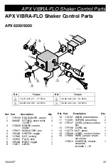
Страница 44: ... in lb 9 0 11 2 N m 1 2 Ref Part Description Qty 1 17N609 PLATE shaker 1 2 17N607 BRACKET mounting armature 1 3 17N608 COIL electromagnetic 230V 1 4 17N606 BLOCK armature 1 5 111800 SCREW cap HH 2 6 113161 SCREW flange HH 5 7 110755 WASHER flat 2 8 17P261 CLAMP loop cushioned 2 9 100527 WASHER flat 2 11 17P658 GUARD shaker 1 13 17P396 LABEL branding shaker 1 Ref Part Description Qty ...

Страница 45: ...NCLOSURE control 1 2 260067 FITTING strain relief 1 2 NPT 2 3 17S020 BOARD control shaker 1 4 17R471 INSULATOR box 1 5 195429 SWITCH toggle 1 6 117625 NUT locking 2 7 123812 PLUG hole 1 8 195428 BOOT toggle 1 9 17J017 LABEL 1 10 116167 KNOB potentiometer 1 11 114391 SCREW grounding 2 12 17R137 CORD junction shaker box 1 13 17P188 CORD set 1 14 119775 NUT panel 1 15 17R346 LABEL control shaker 1 16...

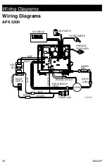
Страница 46: ...iagrams APX 5200 PRESSURE TRANSDUCER POTENTIOMETER POWER PLUG THERMAL SWITCH MOTOR SENSOR LEADS MOTOR LEADS ON OFF SWITCH BROWN BLUE FERRITE JUMPER WIRE BROWN BLUE BLACK BLUE LED DISPLAY AMP SWITCH GREEN GROUND FILTER PWB ti32340a MOTOR ...

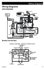
Страница 47: ...ND ON OFF SWITCH BROWN BLUE BROWN BLUE BLUE FILTER COIL APX 8200 ONLY BLACK LED DISPLAY AMP SWITCH GREEN GROUND BROWN BLUE SHAKER CONTROL BOX FILTER PWB ti30615a WIRING DIAGRAM SHAKER CONTROL BOX POTENTIOMETER CONTROL BOARD TOGGLE SWITCH GROUND SCREWS TO CONTROL BOX POWER TO SHAKER COIL JUNCTION CORD JUMPER WIRE ENCLOSURE BROWN BROWN BROWN BROWN GREEN GREEN GREEN BLUE BLUE ti30651a ...

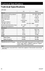
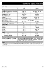
Страница 48: ...20 15 50 60 Environmental temperature range 40 120 F 4 49 C Minimum fluid temperature 40 F 4 C Dimensions Height 42 in 106 7 cm Length 43 in 109 2 cm Width 25 in 63 5 cm Weight 151 lb 69 kg Noise Sound Power 97 dBa 97 dBa Sound Pressure 84 dBa 84 dBa Materials of Construction Wetted materials on all models zinc and nickel plated carbon steel nylon stainless steel PTFE Acetal leather UHMWPE aluminu...

Страница 49: ...ironmental temperature range 40 120 F 4 49 C Minimum fluid temperature 40 F 4 C Dimensions Height 42 in 106 7 cm Length 43 in 109 2 cm Width 25 in 63 5 cm Weight 151 lb 69 kg Noise Sound Power 97 dBa 97 dBa Sound Pressure 84 dBa 84 dBa Materials of Construction Wetted materials on all models zinc and nickel plated carbon steel nylon stainless steel PTFE Acetal leather UHMWPE aluminum tungsten carb...

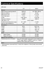
Страница 50: ...ronmental temperature range 40 120 F 4 49 C Minimum fluid temperature 40 F 4 C Dimensions Height 42 in 106 7 cm Length 43 in 109 2 cm Width 25 in 63 5 cm Weight 170 lb 78 kg Noise Sound Power 97 dBa 97 dBa Sound Pressure 84 dBa 84 dBa Materials of Construction Wetted materials on all models zinc and nickel plated carbon steel nylon stainless steel PTFE Acetal leather UHMWPE aluminum tungsten carbi...

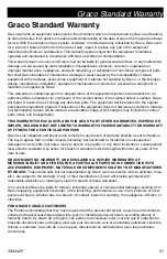
Страница 51: ...s of parts labor and transportation THIS WARRANTY IS EXCLUSIVE AND IS IN LIEU OF ANY OTHER WARRANTIES EXPRESS OR IMPLIED INCLUDING BUT NOT LIMITED TO WARRANTY OF MERCHANTABILITY OR WARRANTY OF FITNESS FOR A PARTICULAR PURPOSE Graco s sole obligation and buyer s sole remedy for any breach of warranty shall be as set forth above The buyer agrees that no other remedy including but not limited to inci...

Страница 52: ...olis International Offices Belgium China Japan Korea GRACO INC AND SUBSIDIARIES P O BOX 1441 MINNEAPOLIS MN 55440 1441 USA Copyright 2017 Graco Inc All Graco manufacturing locations are registered to ISO 9001 www graco com Revision F August 2021 Graco Information For the latest information about Graco products visit www graco com For patent information see www graco com patents TO PLACE AN ORDER c...

Отзывы: