Step 9: R
arts Needed: 3 or 4* Round End Caps
3 – Ratchet Wheels
with the ratchet wheel. The round end cap goes on the left side (opposite the ratchet wheel). Line up
the smaller end of the cap so the grooves match those
rts Needed: 3 or 4* Round End Caps
3 – Ratchet Wheels
with the ratchet wheel. The round end cap goes on the left side (opposite the ratchet wheel). Line up
the smaller end of the cap so the grooves match those
atchet Wheel to Rail Assembly
P
3 or 4* Square End Caps
3 or 4* Square End Caps
*Needed with Optional Fourth Pole
*Needed with Optional Fourth Pole
¾
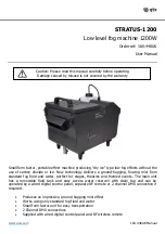
Complete the rail by adding a rail cap on each end. The
¾
Complete the rail by adding a rail cap on each end. The square end cap goes on the right end along
on the rail and push the cap into the rail until it is
set in place.
ight at first. It may help on this first assembly, to put the end
g the end of the rail onto a carpeted floor a couple of
while the ratchet wheel on the middle rail is
the opposite.
To be sure about tooth d
i
square end cap goes on the right end along
on the rail and push the cap into the rail until it is
set in place.
ight at first. It may help on this first assembly, to put the end
g the end of the rail onto a carpeted floor a couple of
while the ratchet wheel on the middle rail is
the opposite.
To be sure about tooth d
i
¾
NOTE:
The end caps may be a little t
caps in place and completely seat them by drivin
times.
¾
NOTE:
The end caps may be a little t
caps in place and completely seat them by drivin
times.
Crib Size
l
70 inch rai
ca
Now add the black ratchet wheel over th
wheel goes on the optional Fourth Pole assemb
nubs on the square end caps.
NOTE! Pay close attention to the toot
ection:
Now add the black ratchet wheel over th
wheel goes on the optional Fourth Pole assemb
nubs on the square end caps.
NOTE! Pay close attention to the toot
ection:
¾
e square pole cap on the right end of each rail (no ratchet
ly). Line up the notches on the Ratchet Wheel with the
h
dir
1.
The ratchet wheel teeth on the two outside
frame,
¾
e square pole cap on the right end of each rail (no ratchet
ly). Line up the notches on the Ratchet Wheel with the
h
dir
1.
The ratchet wheel teeth on the two outside
frame,
round end
p
square end
cap
cog wheel
rails face toward the table side of the
rails face toward the table side of the
2.
¾
2.
¾
irection, you
tchet stop once it is
llustration bottom of
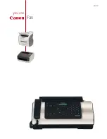
Now put the rails into the frame. This
le
irection, you
tchet stop once it is
llustration bottom of
Now put the rails into the frame. This
le
can double check the fit of the ratchet
can double check the fit of the ratchet
wheel with its ra
assembled (see
wheel with its ra
assembled (see
next page).
next page).
illustration shows the frame from the tab
side, right end. The rails will simply slide
into place as you put them into the proper
grooves.
illustration shows the frame from the tab
side, right end. The rails will simply slide
into place as you put them into the proper
grooves.
¾
See diagram on page 33 for placement
of the fourth pole into the frame.
¾
See diagram on page 33 for placement
of the fourth pole into the frame.
13
Right Frame End Assembly