JUKI MF-7700 Series, Engineer'S Manual
The JUKI MF-7700 Series is a high-performance sewing machine designed for industrial use. Ensure optimal usage with the Engineer's Manual, available for free download on our website. Find comprehensive instructions and helpful tips to maximize productivity and efficiency in your sewing projects. Visit manualshive.com to access this essential manual.
Share
Download


Reviews:
No comments
Related manuals for MF-7700 Series

PRO 100
Brand: Gamma Pages: 11

12K222
Brand: Singer Pages: 29

Sydney
Brand: Kangaroo Pages: 36

1600P-QC -
Brand: Janome Pages: 47

MBS-1500
Brand: MasterCraft Pages: 6

CONTEC HORNET
Brand: Bartell Pages: 20

SEWHANDY MODEL 40K
Brand: Singer Pages: 12

DSK-4000
Brand: dj power Pages: 12

EASY TURF TD-01
Brand: We R memory keepers Pages: 20

BR 90 R
Brand: Kärcher Pages: 15

OKIFAX 5750
Brand: Oki Pages: 154
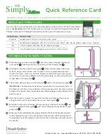
HQ Simply Sixteen
Brand: handi quilter Pages: 2

2-9824
Brand: GE Pages: 18

2-9868
Brand: GE Pages: 20

2-9866
Brand: GE Pages: 2

15638680 (REV. 1 E/S) 29878
Brand: GE Pages: 2

16018110
Brand: GE Pages: 2

2 2-9992 2-9992
Brand: GE Pages: 32


