background image

14

English

8. Electrical connections

The electrical connections are made to screw terminals
which are easily accessible from the front of the signal
isolator (see Figs. 7 to 10) and can accommodate wire
gauges up to 2.5 mm

2

.

Make sure that the cables are not live when
making the connections!

In the case of 

“intrinsically safe”

 explosion

proof versions [EEx ib ] IIC or [EEx ia] IIC, the
supplementary information given on the type
examination certification, the EN 60 079-14
and also local regulations applicable to
electrical installations in explosion hazard
areas must be taken into account.

Note that, ...

... the required electrical insulation and

transmission data agree with the data on
the nameplate of the SINEAX TI 807 (
input signals and 

 output signals)!

... in the case of a signal isolator with 

current

outputs 0...20 mA, the total resistance of the
external leads (receiver plus leads) 

does

not

 exceed the maximum burden of 1000 

(non-Ex version) or 500 

 (Ex version)! See

“Output signal” in Section “5. Technical
data”!

... in the case of a signal isolator with 

voltage

output 0...10 V, the external receiver
connected across the output has a
sufficiently 

high 

internal resistance Ri

A

 in

relation to the SINEAX TI 807 output
impedance of 

500


! See “Output signal” in

Section “5. Technical data”!
The error due to Ri

A

 is:

500 [

] · 100

Ri

A

 [

]

F [%] =

Signal isolator in housing S17 with 

two 

isolation

and transmission channels

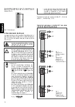
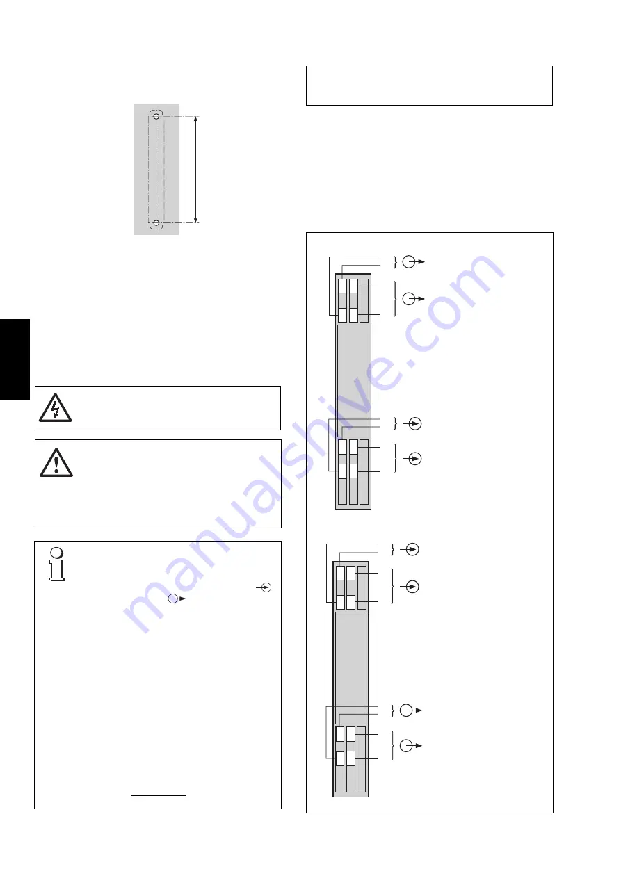
Drill 2 holes in the wall or panel as shown in the drilling pattern
(Fig. 6). Now secure the signal isolator to the wall or panel
using two 4 mm diameter screws.

Fig. 6. Drilling pattern.

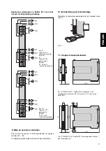
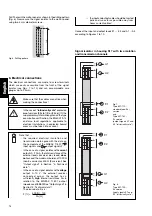
Connect the input and output leads E1 … E3 and A1 … A3
according to Figures 7 to 10.

Fig 7.
Type 807-112…,
standard (non-Ex)
version
and
Type 807-162…,
Ex version
(output signals A1 and
A2 “intrinsically safe”)

Fig. 8.
Type 807-122…,
Ex version
(input signals E1 and
E2 “intrinsically safe”)

1

2

0

1

6

2

7

4

3

9

8

+

A1

E1

+

A2

+

+

+

E2

1

6

2

7

4

3

9

8

+

A1

E1

+

A2

+

+

+

E2

... the input and output cables should be twisted

pairs and run as far as possible away from
heavy current cables!

Содержание SINEAX TI 807-1

Страница 1: ...nts com http www gmc instruments com Betriebsanleitung Passiver DC Signaltrenner SINEAX TI 807 1 Mode d emploi Séparateur galvanique passif SINEAX TI 807 1 Operating Instructions Passive DC signal isolator SINEAX TI 807 1 Camille Bauer AG G O S S E N M E T R A W A T T C A M I L L E B A U E R G O S S E N M E T R A W A T T C A M I L L E B A U E R ...

Страница 2: ...2 ...

Страница 3: ... impérative ment être observés sont marqués des symboles ci contre dans le présent mode d emploi Safety precautions to be strictly observed are marked with following symbols in the Operating Instructions Betriebsanleitung Passiver DC Signaltrenner SINEAX TI 807 1 Mode d emploi Séparateur galvanique passif SINEAX TI 807 1 Operating Instructions Passive DC signal isolator SINEAX TI 807 1 ...

Страница 4: ...Daten Eingangssignal E Gleichstromsignal IE 0 20 mA Max zulässiger Strom 50 mA Spannungsbegrenzung Nicht Ex Ausführung 27 V 5 mit Zenerdiode Ex Ausführung 18 V 5 Ausgangssignal A Gleichstrom oder Gleichspannung Gleichstromsignal IA 0 20 mA Spannungsabfall UV 2 6 V bei der Standard Nicht Ex Ausführung 4 5 V bei Ex Ausführungen Eingangssignale eigensicher 6 1 V bei Ex Ausführungen Ausgangssignale ei...

Страница 5: ...schild gemäss Bild 3 links mit Finger leicht eindrücken bis sie auf der gegenüberliegenden Seite herausspringt Das eingelegte Frontschild ist aus tauschbar und steht zum Anbringen von Vermerken zur Verfügung NachdemWiedereinlegendesFrontschildesindieKlarsicht abdeckung diesewiedereinsetzen DazuKlarsichtabdeckung zuerst unter die untere Halterung führen und mit Finger Bild 3 rechts durch Druck zum ...

Страница 6: ...ürde von 1000 Ω bei der Standard Ausführung und 500 Ω bei der Ex Ausfüh rung nicht überschreitet Vgl Ausgangs signal Abschnitt 5 Technische Daten dass beim Signaltrenner mit Spannungs ausgang 0 10 V die in der Ausgangs signal LeitungparallelvorzusehendenEmp fangs GeräteeinenhohenInnenwiderstand RiA aufweisen hoch inRelationzumInnen widerstand des SINEAX TI 807 von 500 Ω Vgl Ausgangssignal Abschnit...

Страница 7: ...ld 9 Typ 807 113 Standard Nicht Ex Ausführung und Typ 807 163 Ex Ausführung Ausgangssignale A1 A2 und A3 eigensicher Bild 10 Typ 807 123 Ex Ausführung Eingangssignale E1 E2 und E2 eigensicher Signaltrenner im Gehäuse S17 mit drei Trenn und Übertragungskanälen 1 6 2 7 4 3 9 8 11 12 14 13 E2 A3 E3 A1 A2 E1 1 6 2 7 4 3 9 8 11 12 14 13 E2 A3 E3 A1 A2 E1 146 5 17 5 120 0 5 0 145 5 120 134 120 Ø 4 5 6 5...

Страница 8: ... 5 Caractéristiques techniques Signal d entrée E Signal courant continu IE 0 20 mA Courant max 50 mA Limitation de tension Exécution non Ex 27 V 5 par diode zener Exécution Ex 18 V 5 Signal de sortie A Courant continu ou tension continue Sortie en courant continu IA 0 20 mA Chute de tension UV 2 6 V pour l exécution standard non Ex 4 5 V pour les exécutions Ex entrées en sécurité intrinsèque 6 1 V...

Страница 9: ...légère pression sur le capot transparent Fig 3 à gauche jusqu à ce qu il se libère en haut La plaquette signalétique est interchangeable et sert à des annotations diverses Après mise en place de la plaquette remettre le capot transparent en le glissant d abord dans la gorge inférieure et l encliqueter définitivement par une pression du doigt Fig 3 à droite Fig 3 A gauche Enlever le capot transpare...

Страница 10: ...résistancedeslignes n excède pas la charge de 1000 Ω pour l exécution non Ex ou 500 Ω pour l exécution Ex Voir Signal de sortie chapitre 5 Caracté ristiques techniques que pourleséparateuravecsortietension 0 10V lesappareilsrécepteursconnectés en parallèle aient une résistance interne RiA élevée élevée par rapport à la résistance interne de 500 Ω du SINEAX TI 807 Voir Signal de sortie chapitre 5 C...

Страница 11: ...ite pas d entretien Fig 9 Type 807 113 exécution standard non Ex et Type 807 163 exécution Ex Sorties A1 A2 et A3 sécurité intrinsèque Fig 10 Type 807 123 exécution Ex Entrées E1 E2 et E2 sécurité intrinsèque Séparateur galvanique en boîtier S17 avec trois circuits de séparation galvanique Fig 12 SINEAX TI 807 1 boîtier S17 encliqueté sur rail symétrique en chapeau 35 15 mm ou 35 7 5 mm selon EN 5...

Страница 12: ...ata Input signal E DC current signal IE 0 20 mA Max permissible currnet 50 mA Voltage limiter Non Ex version 27 V 5 with zener diode Ex version 18 V 5 Output signal A DC current or DC voltage DC current signal IA 0 20 mA Voltage drop UV 2 6 V for the standard non Ex version 4 5 V for Ex versions input signals intrinsically safe 6 1 V for Ex versions output signals intrinsically safe Max burden 100...

Страница 13: ...t pops out on the opposite side The label in the cover can be replaced and used for notes After replacing the label in the transparent cover the trans parent cover can be snapped into the front of the device again This is done by inserting it behind the edge at the bottom and pressing it gently down and to the rear with the finger until it snaps into place right side of Fig 3 Fig 3 Left Removing t...

Страница 14: ...den of 1000 Ω non Ex version or 500 Ω Ex version See Output signal in Section 5 Technical data in the case of a signal isolator with voltage output 0 10 V the external receiver connected across the output has a sufficiently high internal resistance RiA in relation to the SINEAX TI 807 output impedance of 500 Ω See Output signal in Section 5 Technical data The error due to RiA is 500 Ω 100 RiA Ω F ...

Страница 15: ...requires no maintenance Fig 9 Type 807 113 standard non Ex version and Type 807 163 Ex version output signals A1 A2 and A3 intrinsically safe Fig 10 Type 807 123 Ex version input signals E1 E2 and E2 intrinsically safe Signal isolator in housing S17 with three isolation and transmission channels Fig 12 SINEAX TI 807 1 housing S17 clipped onto a top hat rail 35 15 mm or 35 7 5 mm acc to EN 50 022 1...

Страница 16: ...16 ...

Отзывы: