


Page 6 of 14
Unit Setup
Once the unit is powered up with the above connections, the CAP-DEC 1 unit may be configured as
desired to station-specific preferences including network setup, printer installation, monitoring and interface
options (e.g. logging devices), USB peripherals (e.g. flash drives), etc. (
see Software Setup section below
).
Due to the varied nature of such setup from one station to another, it is impossible to cover all possible
setup procedures. Manufacturer’s instructions should be followed for installation and use of devices such
as printers, USB drives, USB-to-RS232 adapters, logging devices or software, etc.
The CAP-DEC 1
unit must be configured for connectivity with your station’s specific network setup. Again,
due to the varied nature of such systems, it is impossible to cover all possibilities here. The steps
necessary to ensure CAP-DEC 1 connectivity mirror those required for any PC on your network. This
includes opening/unblocking ports for HTTP requests (default: 80) and SMTP activity if email functionality
is desired (default: 25). The CAP-DEC 1 executable (software) should be allowed access through station
firewall and other network protection. If your station’s network utilizes dynamic host control protocol
(DHCP), simply attaching the CAP-DEC 1 to the network should provide connectivity. If static IP
addressing is required, such settings may be entered by navigating to START | Control Panel and
searching for the View Network Connections option. Right-mouse-click the connection to be used and
c
hoose Properties. Contact your station’s network technician for station-specific setup details.
Connections for Operation
Once the unit has been properly configured for operation, interface devices such as a keyboard, mouse
and monitor are not required for normal operation although they may be left attached for monitoring,
testing or further setup. The network cable must remain attached so that the unit is able to receive CAP
alerts and the power cable must remain attached. The following connections must be made to ensure
delivery of CAP-converted EAS alerts between the CAP-DEC 1 unit and the EAS decoder.
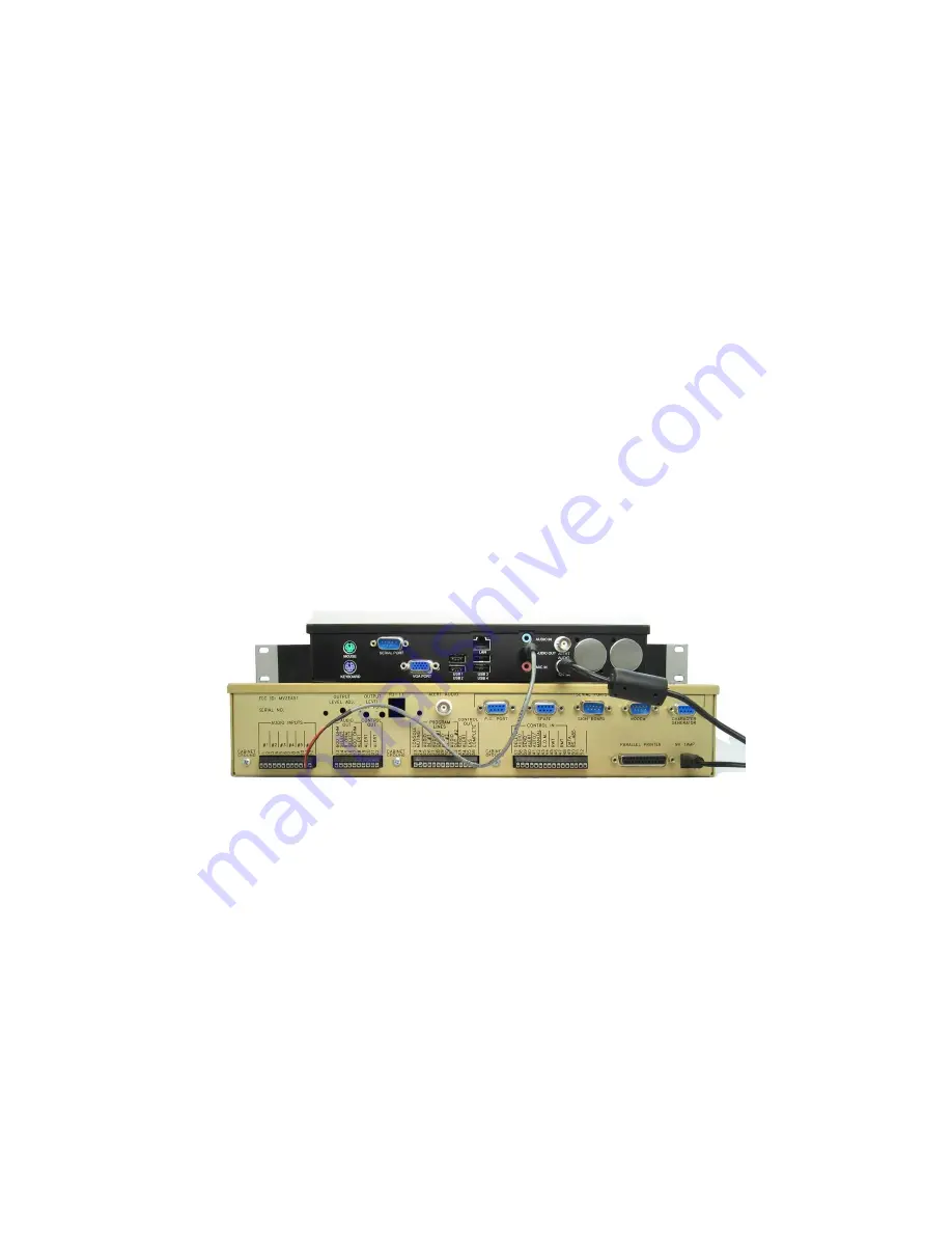
Connected Gorman-Redlich CAP-DEC 1 and EAS1 units
(universal intermediary device configuration)
Use as a Universal Intermediary Device
(With any certified EAS encoder/decoder, including Gorman-Redlich EAS1 products)
1.
Connect the 1/8” TRS plug of the audio cable to the green AUDIO OUT port on the rear of the CAP-
DEC 1 unit. Install the red and black wires of the audio cable into the EAS unit on a channel
capable of monitoring for and parsing frequency shift keyed (FSK) EAS headers (see
encoder/decoder
manufacturer
documentation
for
details).
For Gorman-Redlich EAS1 units, the CAP-DEC 1 should be connected to the next available,
unscanned audio input. For example, if your EAS1 currently scans 5 inputs, the audio cable should
be
connected
to
audio
input
#6
(terminals
11
and
12)
as
shown
above.