
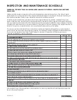


INSPECTION AND MAINTENANCE SCHEDULE
*Federal, state and local codes may require inspection and maintenance checks more often. Please check
the federal, state and local code manuals in your area. Gorbel recommends a certification inspection
interval of no more than one year by a qualified person.
26
10/12 Rev. E
WARNING
Any changes in rolling effort or unusual noises must be immediately identified and corrected. It is not necessary to
lubricate the track or bearings. Lubricating may attract airborne particles and may increase the rolling resistance.
Do not use such substances as WD40®, silicone sprays, oil or grease.
600 Fishers Run, P.O. Box 593
Fishers, NY 14453-0593
© 2012 Gorbel Inc.
All Rights Reserved
GORBEL® TETHER TRACK® SWING ARM INSPECTION AND MAINTENANCE SCHEDULE
ITEM COMPONENT
MAINTENANCE
FREQUENCY*
1
Mounting Bolts
Check that lockwashers are compressed and nuts tightened to
manufacturers specifications.
Every 500 hours
or 3 months
2
Pivot Assemblies Check that lockwashers are compressed. Check for wear on thrust
washers. Grease fittings (use Lubriplate #630-AA or equivalent).
Every 1000 hours
or 6 months
3
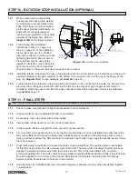
End Stops
Check for full compression of lockwasher. If thru-bolt is exposed,
replace endstops.
Every 2000 hours
or yearly
4
Tether Trolley™
Connector
Check eyenut for wear. Check that clamp plate lockwashers are
compressed. Check that black spring washer is not deformed and is in
place. Confirm spring pin is in place. Check for smooth rolling action.
Recover Trolley only:
Check that guide bushing bolts are tightened to
10 ft-lbs and bushings spin freely.
Every 2000 hours
or yearly
5
Wheels
Check for cracks, pits and/or grooves: all of these increase pull
forces. If any of these conditions exist, wheels should be replaced.
Every 2000 hours
or yearly
6
Accessory Items
Conduct a general inspection of all accessory items.
Every 1000 hours
or 6 months
7
Tether Track®
Swing Arm
Conduct a visual inspection of wall cantilever Swing Arm weldment,
Tether Track® and mast weldment.
Every 1000 hours
or 6 months
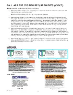
8
Capacity and
Warning Labels
Check that all labels are in place and legible. Replace labels if
damaged or illegible.
Every 2000 hours
or yearly
9
Connecting
Equipment
Inspect all protective equipment connected to the Tether Track®
Anchorage System following the operation and maintenance manuals
provided for each piece of equipment.
As required by
manufacturer
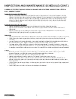
1
2
3
4
5
Free Standing
Swing Arm
Wall Mounted
Swing Arm
WARNING
This product can expose you to chemicals, including acrylonitrile,
which are known to the State of California to cause cancer. For
more information go to:
www.P65Warnings.ca.gov
Distributed by Engineered Fall Protection
Sales@EngineeredFallProtection.com
www.EngineeredFallProtection.com
Tel: (314) 492-4422


