


05
2.3 Description of LED Indicators
Bottom surface of the box
The LED indicators are as follows:
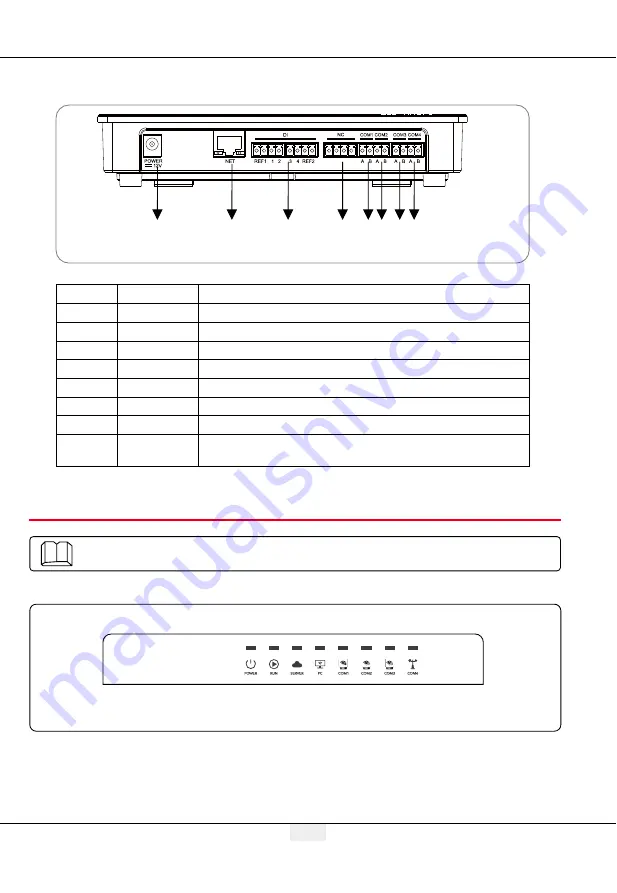
Figure 2.2-6 Bottom View of EzLogger Pro Box
8
7
6
5
4
3
2
1
No.
Port
Port Description
1
POWER
Adapter 12VDC input
2
NET
Ethernet port
3
DI
DRED or RCR function port
4
NC
Function reserved
5
COM1
RS485 communication port 1 for inverter
6
COM2
RS485 communication port 2 for inverter
7
COM3
RS485 communication port 3 for inverter
8
COM4
RS485 communication port 4 for
environmental monitor and other devices
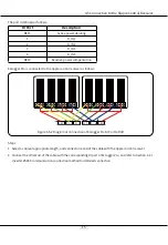
Introduce the meaning of the LED indicators.
2.3 Description of LED Indicators
Figure 2.3-1 Explanatory Drawing of LED Indicators