background image

1

Identifying your Amplifier

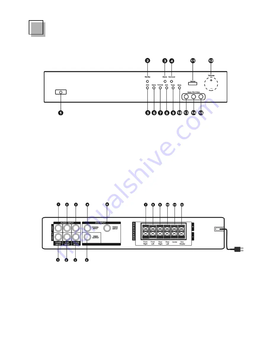
Front Panel

Rear Panel

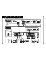
1. Tuner Input connectors
2. AUX Input connectors
3. TV/VCR Input connectors
4. Coaxial DVD Input connector
5. DVD Video Output connector
6. DVD Video Input connector

7. Front Right Speaker terminals
8. Front Left Spearker terminals
9. Rear Right Speaker terminals
10. Rear Left Speaker terminals
11. Center Speaker terminals
12. Subwoofer Speaker terminals

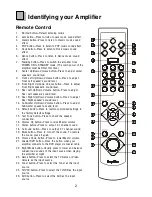
1. Power button
2. Standby indicator
3. Stereo indicator
4. Surround indicator
5. DVD indicator
6. Game indicator
7. TV/VCR indicator
8. AUX indicator

9. Tuner indicator
10. Mute indicator
11. Source button
12. Volume Up/Down button
13. Game Input (RIGHT) connector
14. Game Input (LEFT) connector
15. Game Input connector

Note: The layout of the panels are subject to change on revising.

Содержание GHC 56 PRO

Страница 1: ...Am Am Am Amplif plif plif plif plifier A ier A ier A ier A ier Audio Sy udio Sy udio Sy udio Sy udio Sys s s s st t t t tem em em em em 82 136 00053 HELPLINE Goodmans product information helpline 08708730080 GHC 56 PRO GHC 56 PRO GHC 56 PRO GHC 56 PRO GHC 56 PRO User Guide ...

Страница 2: ... first powered up and reduced the volume setting by pressing the volume button on the remote control Once this has been done then proceed with the TEST TONE and VOLUME AD JUSTMENTS as detailed on page 4 of the instruction manual Note that the vol ume settings are maintained when powering off using the remote control The volume settings will need to be reset if the power button on the front panel o...

Страница 3: ...r Right Speaker terminals 10 Rear Left Speaker terminals 11 Center Speaker terminals 12 Subwoofer Speaker terminals 1 Power button 2 Standby indicator 3 Stereo indicator 4 Surround indicator 5 DVD indicator 6 Game indicator 7 TV VCR indicator 8 AUX indicator 9 Tuner indicator 10 Mute indicator 11 Source button 12 Volume Up Down button 13 Game Input RIGHT connector 14 Game Input LEFT connector 15 G...

Страница 4: ...Subwoofer Up Down Volume button Press to adjust Subwoofer speaker s sound level 14 Default button Press to restore customized settings to the factory default settings 15 Test Tone button Press to check the speaker connection 16 Volume Up button Press to raise Master volume 17 Stereo button Press to output 2 1 channel sound 18 Surround button Press to output 5 1 channel sound 19 Mute button Press t...

Страница 5: ...e individual speaker s volume level Test Tone Checking 1 Press the TEST TONE button when the amplifier is in POWER ON mode 2 The amplifier will output a test tone to the 6 spearkers in turn 3 While the test tone is playing use the individual speaker volume buttons to adjust the volume from each speaker Note To stop the test tone press the test tone button again Basic Operation 1 Press the POWER bu...

Страница 6: ...ult setting is NORMAL Using Amplifier Before starting using the amplifier please connect all the audio devices to the device first Refer to the included Amplifier Connection Diagram Night Mode 1 Press the button on the remote control 2 The Mute LED on the front panel of the amplifier will flash 3 The amplifier will automatically lower and balance any sudden burst of loudness from the input souce b...

Страница 7: ...d press the STEREO button will force the amplifier to manually change and playback the disc as a stereo sound system and the sound will only come out of the 2 front speakers plus the subwoofer Surround Mode 1 Press the SURROUND button 2 The amplifier will playback the input source from the 6 speakers Note The amplifier will auto detect and playback whatever was recorded on the DVD or audio disc If...

Страница 8: ...ent Automatic test tone with speaker level adjustment Audio EQ 2CH to 6CH Pro Logic II function for external audio input Night mode from DRC dynamic range compression function LED Indicator Game Port input on the front panel Terminal and I O section Input front A V RCA Game port x1 Input rear Audio RCA White Red x3 Tuner TV VCR AUX Input rear Video RCA Yellow x 1 Input rear Digital audio input coa...

Страница 9: ...L Video Camera OR R L AUDIO OUTPUT AUDIO OUT AUDIO OUT VIDEO OUT AUDIO OUT AUDIO OUT VIDEO OUT A B C D E A Amplifier Amplifier COAXIAL 1 2 3 Speaker Connection VCR G R L F TV SET A Amplifier B Game Console C Video Camera D DVD E Tuner F TV G VCR RED WHITE YELLOW Front Right Front Left Rear Right Rear Left Center Sub woofer White Red Yellow White Red Yellow ...

Страница 10: ...rs B Game F TV C Video Camera G VCR D DVD CABLES F TV F TV E Tuner Connecting to a TV Game 2 Y ellow Video cables Red White Audio cables 2 Y ellow Video cables Coaxial cable Red White Audio cables 2 Y ellow Video cables Red White Audio cables F TV Connecting to a Video Camera Connecting to a DVD Connecting to a Tuner Connecting to a VCR Connections ...

Отзывы: