


14
E
XTERIOR
MASONRY
C
HIMNEYS
- C
ATEGORY
I F
URNACES
O
NLY
NOTE: In a horizontal installation the air conditioning coil
must be adequately supported by proper brackets and
supports. Inadequate coil support can result in furnace cabinet
distortion and air leakage.
Counterflow units
are shipped with the induced draft blower
discharging from the top of the furnace. (“Top” as viewed for a
counterflow installation.)
Vent the furnace in accordance with the National Fuel Gas
Code NFPA54/ANSI Z223.1-latest edition. In Canada, vent the
furnace in accordance with the national standard of Canada,
CAN/CSA B149.1 and CAN/CSA B149.2- latest editions and
amendments.
N
EVER
ALLOW
THE
PRODUCTS
OF
COMBUSTION
,
INCLUDING
CARBON
MONOXIDE
,
TO
ENTER
THE
RETURN
DUCTWORK
OR
CIRCULATION
AIR
SUPPLY
.
WARNING
E
XTERIOR
M
ASONRY
C
HIMNEYS
(C
ATEGORY
I F
URNACES
O
NLY
)
An exterior masonry chimney is defined as a “Masonry” chim-
ney exposed to the outdoors on one or more sides below the
roof line.” The ability to use a clay lined masonry chimney
depends on a parameter not associated with interior chimneys.
This variable is the geographic location of the installation. Re-
searchers have discovered that the winter design temperatures
have a direct impact on the suitability of this type of venting. In
most situations, the existing masonry chimneys will require a
properly sized metallic liner.
P
OSSIBILITY
OF
PROPERTY
DAMAGE
,
PERSONAL
INJURY
OR
DEATH
DAMAGING
CONDENSATION
CAN
OCCUR
INSIDE
MASONRY
CHIMNEYS
WHEN
A
SINGLE
FAN
‐
ASSISTED
C
ATEGORY
I
APPLIANCE
(80%
AFUE
FURNACE
)
IS
VENTED
WITHOUT
ADEQUATE
DILUTION
AIR
.
D
O
NOT
CONNECT
AN
80%
FURNACE
TO
A
MASONRY
CHIMNEY
UNLESS
THE
FURNACE
IS
COMMON
VENTED
WITH
A
DRAFT
HOOD
EQUIPPED
APPLIANCE
OR
THE
CHIMNEY
IS
LINED
WITH
A
METAL
LINER
OR
T
YPE
B
METAL
VENT
.
A
LL
INSTALLATIONS
USING
MASONRY
CHIMNEYS
MUST
BE
SIZED
IN
ACCORDANCE
WITH
THE
APPROPRIATE
VENTING
TABLES
.
I
F
AN
80%
FURNACE
IS
COMMON
VENTED
WITH
A
DRAFT
HOOD
EQUIPPED
APPLIANCE
,
THE
POTENTIAL
FOR
CONDENSATION
DAMAGE
MAY
STILL
EXIST
WITH
EXTREMELY
COLD
CONDITIONS
,
LONG
VENT
CONNECTORS
,
EXTERIOR
CHIMNEYS
,
OR
ANY
COMBINATION
OF
THESE
CONDITIONS
.
T
HE
RISK
OF
CONDENSATION
DAMAGE
IS
BEST
AVOIDED
BY
USING
MASONRY
CHIMNEY
AS
A
PATHWAY
FOR
PROPERLY
SIZED
METAL
LINER
OR
T
YPE
B
METAL
VENT
.
WARNING
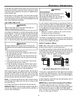
Wash
Clay Tile Size: 8" x 8" x12"
(Each x 24" Length)
1/2" to 1" Air Space
Second Floor
First Floor
Attic Floor
Roof Line
Throat
Damper
Breech
Clean Out
Fan Assisted
Forced Air
Furnace
Natural Draft
Water Heater
Water Heater
Vent Connector
Basement Floor
F.A.F. Vent
Connector
Typical Multiple Flue Clay Tile Chimney
C
HECKLIST
S
UMMARY
This checklist serves as a summary of the items to be checked
before venting an 80+ furnace into a masonry chimney. In addi-
tion, we recommend that a qualified serviceman use this check-
list to perform a yearly inspection of the furnace venting sys-
tem.
This checklist is only a summary. For detailed information on
each of the procedures mentioned, see the paragraph refer-
enced with each item.
This inspection is based upon a draft topical report, “Masonry
Chimney Inspection and Relining”, issued by the Gas Research
Institute. While not yet finalized, we believe this report repre-
sents the best information on this subject which is currently
available.


