


11
L
OCATION
R
EQUIREMENTS
AND
C
ONSIDERATIONS
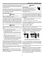
T O P
B1-V EN T
S IN G LE
(P LE N U M )
1"
6"
1"
3"
0"
1"
VEN T
SID ES
F R O N T
B AC K
Top clearance for horizontal configuration - 1"
H
ORIZONTAL
I
NSTALLATION
Line contact to framing is permitted when installed in the hori-
zontal configuration. Line contact is defined as the portion of
the cabinet that is formed by the intersection of the top and
side. ACCESSIBILITY CLEARANCE, WHERE GREATER,
SHOULD TAKE PRECEDENCE OVER MINIMUM FIRE PRO-
TECTION CLEARANCE. A gas-fired furnace for installation in
a residential garage must be installed so that the ignition source
and burners are located not less than eighteen inches (18")
above the floor and is protected or located to prevent physical
damage by vehicles. A gas furnace must not be installed di-
rectly on carpeting, tile, or other combustible materials other
than wood flooring.
F
URNACE
S
USPENSION
If suspending the furnace from rafters or joist, use 3/8" threaded
rod and 2”x2”x3/8” angle iron as shown below. The length of
rod will depend on the application and the clearances neces-
sary.
Suspended Furnace
E
XISTING
F
URNACE
R
EMOVAL
NOTE:
When an existing furnace is removed from a venting
system serving other appliances,
the venting system may be
too large to properly vent the remaining attached appliances.
The following vent testing procedure is reproduced from the
American National Standard/National Standard of
Canada for Gas-Fired Central Furnaces ANSI Z21.47-Lat-
est Edition, CSA-2.3-Latest Edition Section 1.23.1.
The fol-
lowing steps shall be followed with each appliance connected
to the venting system placed in operation, while any other ap-
pliances connected to the venting system are not in operation:
a.
Seal any unused openings in the venting system;
•
Do not connect this furnace to a chimney flue that
serves a separate appliance designed to burn solid
fuel.
•
For counterflow installations, the air conditioning coil
must be downstream from the heat exchanger of the
furnace.
•
Counterflow installation over a noncombustible floor.
Before setting the furnace over the plenum opening,
ensure the surface around the opening is smooth and
level. A tight seal should be made between the furnace
base and floor by using a silicon rubber caulking
compound or cement grout.
•
Counterflow installation over a combustible floor. If
installation over a combustible floor becomes
necessary, use an accessory subbase (see
Specification Sheet applicable to your model for details).
A special accessory subbase must be used for upright
counterflow unit installations over any combustible
material including wood. Follow the instructions with
the subbase for proper installations. Do not install the
furnace directly on carpeting, tile, or other combustible
material other than wood flooring. (
NOTE
: The subbase
will not be required if an air conditioning coil is installed
between the supply air opening on the furnace and the
floor.
Top - 1"
Side
Clearance - 1"
Back - 0"
Front Clearance - 3"
Vent Pipe Clearance to Combustibles-
6" using Single Wall Connector or 1"
using B-1 vent.
•
Adequate combustion/ventilation air must be supplied
to the closet.
•
Furnace must be
completely
sealed to floor or base.
Combustion/ ventilation air supply pipes must terminate
12" from top of closet and 12" from floor of closet. DO
NOT remove solid base plate for side return.
•
Return air ducts must be
completely
sealed to the
furnace and terminate outside the enclosure surfaces.
C
LEARANCES
AND
A
CCESSIBILITY
Unobstructed front clearance of 24"
for servicing
is recom-
mended.


