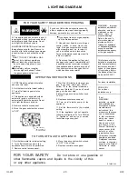
Goodman GMNTE Скачать руководство пользователя страница 20

IO-231

  6/03

20

LIGHTING DIAGRAM

call  a  qualified  service  technician. 

will not operate, don't try  to  repair it, 

7. Wait five (5) minutes to clear out any

the control system and any gas control

the appliance and to replace any part of

a qualified service technician to inspect 

has been under water. Immediately call

D. Do not use this appliance if any part

tools. If the gas control switch or knob

control   switch  or  knob.  Never   use

C. Use only your hand to move the gas

which has been under water.

If you do not follow these instructions exactly, 

a fire or explosion may result causing property

If you cannot reach your gas supplier,

damage, personal injury or loss of life.

FOR YOUR SAFETY READ BEFORE OPERATING

Force or attempted repair may result in

10. Turn  on  all  electric  power  to  the

other  flammable  vapors  and  liquids  in  the  vicinity  of  this

  Do  not  store  or  use  gasoline  or

4. Move the gas control switch or knob

follow the instructions "To Turn Off Gas

5. Replace control access panel.

To  Appliance"  and  call  your  service 

12. If  the  appliance  will  not  operate,

11. Set  the  thermostat  to  the  desired

9. Replace control access panel.

8. Move the gas control switch or knob

above on this label. If  you  don't  smell

Follow  "B"  in  the  safety  information 

gas. If  you  then  smell  gas,  STOP!

3. Remove control access panel.

1. Set the thermostat to its lowest setting.

appliance if service is to be performed.

2. Turn off all electric power to the 

or  any  other  appliance.

FOR  YOUR  SAFETY

TO TURN OFF GAS TO APPLIANCE

X

X

X

X

E

H I

P,M

F
F

O

ON

C

to "OFF". Do not force.

technician or gas supplier.

floor.

is heavier than air and will settle on the 

OPERATING INSTRUCTIONS

1. STOP! Read the safety information

from a neighbor's phone. Follow

do not use any telephone in your

Do not touch any electric switch;

Do not try to light any appliance.

WHAT TO DO IF YOU SMELL GAS

the gas suppliers instructions.

Immediately call your supplier

automatically lights the burners. Do not

6. Move the gas control switch or knob

try to light the burners by hand.
5. Remove control access panel.

2. Set the thermostat to lowest setting.
3. Turn off all electric power to the

4. This appliance is equipped with an 

automatic  ignition  system  which

above on this label.

appliance.

to "OFF".

building.

to "ON".

appliance.

setting.

gas, go to the next step.

a fire or explosion.

A. This appliance does not have a pilot. It

is equipped with an ignition device which

automatically lights the burners. Do not

B. BEFORE OPERATING smell around

the appliance area for gas. Be sure to 

smell next to the floor because some gas

try to light the burners by hand.

call the fire department.

B14933-240

installation only.

PGB & PGJ

For  outdoor

installed in accordance

This furnace must be

with the manufacturers

the National Fuel Gas

Code, ANSI Z223.1.

codes. In the absence

of local codes, follow

For indoor installation.

instructions and local

WARNING:

installation,  adjustment,

maintenance  can

alteration, service or

or the gas supplier.

property damage.

provided with this

information manual

Refer to the user's

or  additional information

installer, service agency

consult a qualified

furnace. For assistance

cause   injury   or

Improper

GAS CONTROL

IN "ON" POSITION

SWITCH SHOWN 

If not 
WARNING:

installed,  operated
and maintained in

accordance with the

manufacturer's
instructions,  this

product could expose
you  to  substances

in  fuel  combustion
which  can  cause

death  or  serious
illness  and  which

are  known  to  the
State of California to

cause cancer, birth
defects  or  other

reproductive harm.
This product contains

fiberglass  insulation.
Fiberglass  insulation

contains  a  chemical
known by the State of

California  to  cause 
cancer.

W A R N I N G


Содержание GMNTE

Страница 1: ...NOT USE THIS FURNACE IF ANY PART HAS BEEN UNDERWATER IMMEDIATELY CALL A QUALIFIED SERVICE TECHNICIAN TO INSPECT THE FURNACE AND TO REPLACE ANY PART OF THE CONTROL SYSTEM AND ANY GAS CON TROL THAT HAS...

Страница 2: ...t switch Roll out switch Transformer Door interlock switch Air pressure switch Induced draft blower BURNER ASSEMBLY Burners Manifold Orifices Gas Valve Igniter Flame sensor MISCELLANEOUS Wrapper Acces...

Страница 3: ...e with the current CAN CGA B149 1 2 Gas Installation Codes local plumbing or waste water codes and other applicable codes Additional helpful publications available from the NFPA are NFPA 90A Installat...

Страница 4: ...es equal to or less than 1 2 psig 3 5 kPa MIN CLEARANCES TO COMBUSTIBLE SURFACES Unobstructed front clearance of 24 for servicing is recommended RIGHT SIDE 1 VENT 0 REAR 0 LEFT SIDE 1 TOP OF PLENUM 1...

Страница 5: ...in ANSI Z221 3 section 5 3 When installed as a non direct vent furnace in an area which is deemed as a confined area see ANSI Z223 1 section 1 7 Space Confined the requirements are as follows All Com...

Страница 6: ...CTION BOOKLET THE VENT MUST TERMINATE OUTDOORS VENT COMBUSTION AIR SUPPLY PIPE LENGTHS Elbows must be long radius types Quarter bends or DWV The maximum length of the vent pipe and the combustion air...

Страница 7: ...vent terminal within four 4 feet of an adjacent building DIRECT VENT INSTALLATION DO NOT locate the vent terminal within twelve 12 inches of an operable window or door NON DIRECT VENT INSTALLATION DO...

Страница 8: ...nstructions Failure to follow these instructions can cause products of combustion including CARBON MONOXIDE to enter the building This appliance may be horizontally vented through an exterior wall See...

Страница 9: ...ns are not available a condensate pump may be employed This condensate pump must be constructed of corrosion resistant materials It must also have an auxiliary switch that will shut down the furnace i...

Страница 10: ...IO 231 6 03 10 DRAIN CONNECTIONS UPFLOW LEFT DOWNFLOW LEFT SIDE DOWNFLOW RIGHT SIDE UPFLOW RIGHT SIDE...

Страница 11: ...diameters and length in ft 3 hr with a pressure drop of 0 3 W C and a specific gravity of 0 60 natural gas After the length of pipe has been determined select the pipe size which will provide the mini...

Страница 12: ...NNECTIONS The electrical requirements are 115Volts 60 Hz 1 Ph A separate supply line with a current overload device and a manual switch where required must be installed Type T wire or equivalent with...

Страница 13: ...0 Btu ft3 ALTITUDE NAT GAS ORIFICE SIZE 0 1 999 45 2 000 2 999 46 3 000 3 999 47 4 000 4 999 47 5 000 5 999 47 6 000 7 000 48 The input to the furnace must be checked AFTER reorificing For altitudes a...

Страница 14: ...D CHECK OUT PROCEDURE General In most cases the safety controls are wired is series with the W leg It is imperative that these switches remain in the circuit Never jumper relocate unless as noted on t...

Страница 15: ...s blocked or dirty filters Circulating air filters must be inspected monthly for dirt accumulation and replaced if necessary Failure to maintain clean filters can cause premature heat exchanger failur...

Страница 16: ...78 68 1264 68 351 540 1058 68 1523 68 468 720 Norm 975 61 1404 61 1 5 390 600 Norm 1175 61 1692 61 2 0 520 800 1073 56 1544 56 429 660 1293 56 1861 56 572 880 945 63 1361 63 468 720 1058 68 1523 68 2...

Страница 17: ...ollowing figure for switch positions and their corresponding taps Turn off power to furnace for a minimum of 10 sec onds allowing motor to reset and recognize new speed selection Turn on power to furn...

Страница 18: ...will remain inoperable until this situation is corrected The venter blower is energized The vent pressure switch will close when it detects a pressure in excess of its setting If the pressure switch f...

Страница 19: ...n the heat exchanger perform the following Adjust the room thermostat to its lowest setting Turn off the gas and electric supply to the furnace Remove the control access door Open the gas supply union...

Страница 20: ...se any telephone in your Do not touch any electric switch Do not try to light any appliance WHAT TO DO IF YOU SMELL GAS the gas suppliers instructions Immediately call your supplier automatically ligh...

Страница 21: ...SURFACE IGNITION RELAY COM HI BL R SO GV LS P P ROS Y YLO G W 2 R W 1 BLUE WIRE COLOR CODE ORANGE GREEN BROWN BLACK PVR2 POWER VENT RELAY HIGH FIRE PVR1 POWER VENT RELAY LOW FIRE ROS ROLLOUT SWITCH PV...

Страница 22: ...ent causes of product failure They are simple to service and forgiving to operate We use quality materials and components Finally every unit is run tested before it leaves the factory That s why we kn...

Отзывы: