


IO-231
6/03
11
GAS PIPING & GAS PIPE CAPACITY TABLE
Check the rating plate to make certain that the gas supplied
is compatible with the unit requirements. Care should be
taken after the installation of this appliance that the gas
control valve is not subjected to high gas supply line
pressure.
In making connections, avoid strains as they may cause
noise and damage the controls. Always use a back-up
wrench when tightening the gas supply pipe to the gas
control valve. Check for leaks in the gas supply using soap
bubbles or other approved methods.
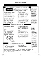
NEVER USE AN OPEN FLAME TO CHECK FOR GAS
LEAKS. THIS PRACTICE MAY CAUSE A FIRE,
EXPLOSION, BODILY HARM OR PROPERTY DAMAGE.
Pipe joint compound must be resistant to the action of L.P.
gas. When connecting the gas service to the furnace, a
ground joint union and manual shutoff must be installed
exterior to the furnace cabinet and located in the same
room so the control assembly may be easily removed.
The valve should be readily accessible for turning on or
off. A capped sediment trap, sometimes called a drip leg,
must be installed in the gas supply pipe as close to the
furnace as possible. The sediment trap must incorporate
a change of gas flow direction.
Refer to local codes or the previously mentioned
publications for proper location and size of the manual
shutoff and sediment trap lengths.
The gas pipe must be sized to eliminate undue pressure
drop. See pipe capacity table or consult your local utility.
Both the supply and manifold pressure must be measured
with all gas burning appliances running using the pressure
tap on the gas valve and the pressure adjusted if
necessary.
All gas piping must conform to local codes, or in the
absence of local codes, to the National Fuel Gas Code
ANSI Z223.1 and / or CAN/CGA B149 Installation Codes.
Note:
Copper tubing must not be used for natural gas
installations where more than .3 grains of hydrogen sulfide
per 100 standard cubic feet of gas is present. (If the
quantities of hydrogen sulfide cannot be verified, do not
use copper).
FOR INSTALLATIONS IN THE COMMONWEALTH OF
MASSACHUSETTS SEE FUEL GAS AND PLUMBING
CODE 248 CMR: APPENDIX C.
Pipe
Size*
½
¾
1
1 ¼
1 ½
10
132
278
520
1050
1600
20
92
190
350
730
1100
Length
30
73
152
285
590
890
of
40
63
130
245
500
760
Pipe
50
56
115
215
440
670
in Feet
60
50
105
195
400
610
70
46
96
180
370
560
80
43
90
170
350
530
*Nominal size of iron pipe in inches.
Capacity of gas pipe of different diameters and length in
ft
3
/hr. with a pressure drop of 0.3" W.C. and a specific
gravity of 0.60 (natural gas).
After the length of pipe has been determined, select the
pipe size, which will provide the minimum cubic feet per
hour of gas flow for the required input of the appliance. In
the case where more than one appliance utilizes the same
supply pipe be sure to consider the sum of all appliances.
The cubic feet of gas required for the appliances should
be determined using the following formula;
Cubic feet of Gas input of appliance (BTU/hr.)
gas required Heating value of gas (BTU/ft.
3
)
The gas input of the appliance is marked on the
specification plate. The heating value of the gas may be
determined by contacting the gas utility or gas supplier.
CIRCULATING AIR SUPPLY AND RETURN AIR
The circulating air supply may be taken from; 1) Outside
the building, 2) return ducts from several rooms, 3) central
return, 4) any combination of the above.
When a cooling coil is not installed it is recommended
that the supply duct have an access panel so the heat
exchanger can be viewed. This panel shall be of sufficient
size to permit the entrance of a light or probe to assist in
the observation of the heat exchanger integrity or sampling
the air stream. It should be sealed to prevent air leakage
during normal operation.
Return air from one dwelling shall not be discharged into
another dwelling through the heating system.
There shall be a positive separation between combustion
air and return air.
Do not obtain return air from a hazardous or insanitary
location or a refrigeration machinery room or any room or
space having any fuel-burning appliances therein.
Note:
When a combination of outdoor and indoor air is uti-
lized the system should be designed and adjusted such
that the temperature reaching the appliance will not drop
=
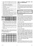
CAUTION
If the local utility permits the use of a flexible gas connector -
ALWAYS USE A NEW FLEXIBLE CONNECTOR.
DO NOT
USE FLEXIBLE GAS LINES THAT HAVE SERVICED ANOTHER
APPLIANCE. AFTER A PERIOD OF TIME THESE LINES MAY
BECOME BRITTLE AND CAN DEVELOP LEAKS. The connec-
tions to a flexible gas line must be made outside of the furnace
cabinet.
CAUTION
DO NOT take return air from bathrooms, kitchens, furnace
rooms, garages, utility/laundry rooms or cold areas. If outside
air is utilized, it should not be taken from within 10 feet of an
appliance vent outlet, a vent opening or a plumbing drainage
system, or the discharge from an exhaust system unless the
outlet is three (3) feet above the outside air inlet. DO NOT take
return air from an area where it can pick-up objectionable odors,
fumes, or flammable vapors.