Goodman GMNTE Скачать руководство пользователя страница 17

IO-231

6/03

17

All furnaces are shipped with heating speed set at “B” and
cooling speed set at “D”. Use the following procedure to
select the heating and cooling speed needed for your unit.
Use the CFM LED (green), adjacent to the integrated con-
trol module fuse to verify airflow quantity.  The green CFM
LED blinks once for each 100 CFM of airflow.

1. Determine the tonnage of the cooling system installed

with the furnace. If the cooling capacity isin BTU/hr di-
vide it by 12,000 to convert capacity to TONs.

Example:

Cooling Capacity of 30,000 BTU/hr.
30,000/12,000 = 2.5 Tons

2. Determine the proper air flow for the cooling system.

Most cooling systems are designed to work with air
flows between 350 and 450 CFM per ton.
Most manufacturers recommend an air flow of about
400 CFM per ton.

Example:

 2.5 tons X 400 CFM per ton = 1000 CFM

The cooling system manufacturer’s instructions must be
checked for required air flow.  Any electronic air cleaners
or other devices may require specific air flows, consult in-
stallation instructions of those devices for requirements.

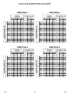
3. Knowing the furnace model, locate the high stage cool-

ing air flow data in the following airflow tables. Look up
the cooling air flow determined in step 2 and find the
required cooling speed and adjustment setting.

Example:

A GMNTE080-4 furnace installed with a

2.5 ton air conditioning system.  The air flow needed is
1000 CFM. Looking at the cooling speed chart for
GMNTE080-4, find the air flow closest to 1000 CFM. A
cooling airflow of 990 CFM can be attained by setting
the cooling speed to “C” and the adjustment to “-” (mi-
nus).

NOTE:

  Continuous Fan Speed will be 38% of high stage

cooling.

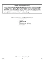
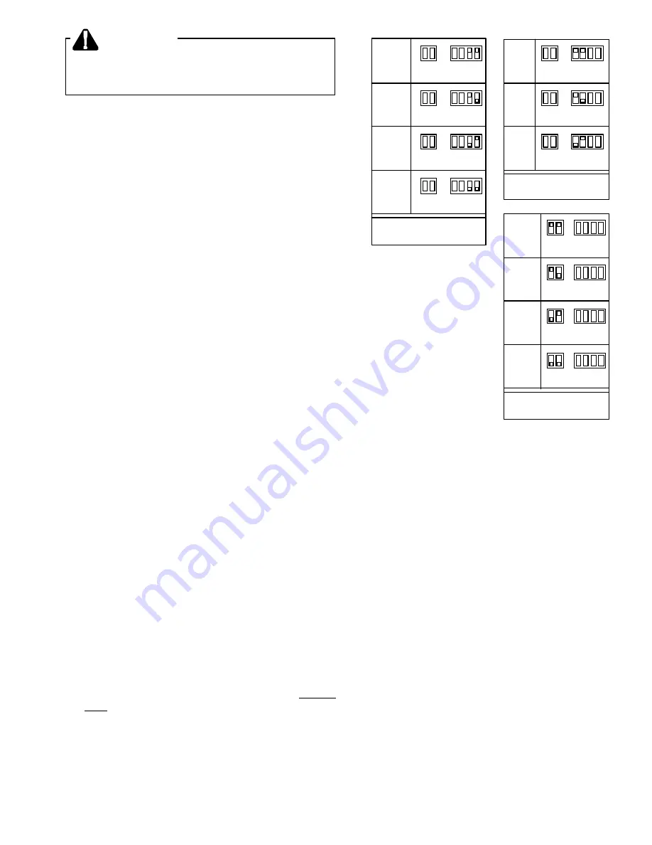
4. Locate the blower speed selection DIP switches on

the integrated control module.  Select the desired “cool-
ing” speed tap by positioning switches 1 and 2 appro-
priately.  Select the desired “adjust” tap by positioning
switches 3 and 4 appropriately.  Refer to the following
figure for switch positions and their corresponding taps.
Turn off power to furnace for a minimum of  10 sec-
onds, allowing motor to reset and recognize new speed
selection.  Turn on power to furnace and place the unit
into cooling mode.  Allow blower to ramp up to full speed.
Verify CFM by counting the number of times the green
CFM LED blinks.

O
F
F

O
F
F

8 7

4 3 2 1

O
F
F

O
N

8 7

4 3 2 1

O

N

O

F
F

8 7

4 3 2 1

O
N

O
N

8 7

4 3 2 1

Cooling

Speed

Tap A

Cooling

Speed

Tap B

Cooling

Speed

Tap C

Cooling

Speed
Tap D

*

Cooling Speed Taps

(

*

 indicates factory setting)

O
F
F

O
F
F

8 7

4 3 2 1

O
F
F

O
N

8 7

4 3 2 1

O
N

O
F
F

8 7

4 3 2 1

O
N

O
N

8 7

4 3 2 1

Heating

Speed

Tap A

Heating

Speed

Tap B

Heating

Speed
Tap C

Heating

Speed
Tap D

Heating Speed Taps

(

*

 indicates factory setting)

*

O
F
F

O
F
F

8 7

4 3 2 1

O
F
F

O
N

8 7

4 3 2 1

O
N

O
F
F

8 7

4 3 2 1

Normal

+ (Plus)

Adjust

- (Minus)

Adjust

Adjust  Taps

(

*

 indicates factory setting)

*

5. Select the heating speed from the heating speed chart

in the specification sheet for your model.  The adjust
setting (already established by the cooling speed se-
lection) determines which set of speeds are available.
The selected speed must provide a temperature rise
within the rise range listed with the particular model.

Example:

The GMNTE080-4 is set for 990

CFM on

cooling, the “ADJUST” is set to “-” (minus). The four
heating speeds available are “A Minus”, “B Minus”, “C
Minus”, and “D Minus”.   “A Minus” has a rise of 63

°

F

for both stages which is within the 35-65°F rise range
for the GMNTE080-4. This setting will keep electrical
consumption to a minimum.  Set the “Heat” speed DIP
switches to “A”.

6. Select the desired “heating” speed tap by positioning

switches 7 and 8 appropriately.  Refer to figure above.
Turn off power to furnace for a minimum of 10 sec-
onds, allowing motor to reset and recognize new speed
selection.  Turn on power to furnace and place the unit
into heating mode.  Allow blower to ramp up to full
speed.  Verify selected CFM by counting the green
CFM LED blinks.

WARNING

TO AVOID DEATH OR PERSONAL INJURY DUE TO ELEC-
TRICAL SHOCK, TURN OFF POWER TO THE FURNACE
BEFORE CHANGING SPEED TAPS.

Содержание GMNTE

Страница 1: ...NOT USE THIS FURNACE IF ANY PART HAS BEEN UNDERWATER IMMEDIATELY CALL A QUALIFIED SERVICE TECHNICIAN TO INSPECT THE FURNACE AND TO REPLACE ANY PART OF THE CONTROL SYSTEM AND ANY GAS CON TROL THAT HAS...

Страница 2: ...t switch Roll out switch Transformer Door interlock switch Air pressure switch Induced draft blower BURNER ASSEMBLY Burners Manifold Orifices Gas Valve Igniter Flame sensor MISCELLANEOUS Wrapper Acces...

Страница 3: ...e with the current CAN CGA B149 1 2 Gas Installation Codes local plumbing or waste water codes and other applicable codes Additional helpful publications available from the NFPA are NFPA 90A Installat...

Страница 4: ...es equal to or less than 1 2 psig 3 5 kPa MIN CLEARANCES TO COMBUSTIBLE SURFACES Unobstructed front clearance of 24 for servicing is recommended RIGHT SIDE 1 VENT 0 REAR 0 LEFT SIDE 1 TOP OF PLENUM 1...

Страница 5: ...in ANSI Z221 3 section 5 3 When installed as a non direct vent furnace in an area which is deemed as a confined area see ANSI Z223 1 section 1 7 Space Confined the requirements are as follows All Com...

Страница 6: ...CTION BOOKLET THE VENT MUST TERMINATE OUTDOORS VENT COMBUSTION AIR SUPPLY PIPE LENGTHS Elbows must be long radius types Quarter bends or DWV The maximum length of the vent pipe and the combustion air...

Страница 7: ...vent terminal within four 4 feet of an adjacent building DIRECT VENT INSTALLATION DO NOT locate the vent terminal within twelve 12 inches of an operable window or door NON DIRECT VENT INSTALLATION DO...

Страница 8: ...nstructions Failure to follow these instructions can cause products of combustion including CARBON MONOXIDE to enter the building This appliance may be horizontally vented through an exterior wall See...

Страница 9: ...ns are not available a condensate pump may be employed This condensate pump must be constructed of corrosion resistant materials It must also have an auxiliary switch that will shut down the furnace i...

Страница 10: ...IO 231 6 03 10 DRAIN CONNECTIONS UPFLOW LEFT DOWNFLOW LEFT SIDE DOWNFLOW RIGHT SIDE UPFLOW RIGHT SIDE...

Страница 11: ...diameters and length in ft 3 hr with a pressure drop of 0 3 W C and a specific gravity of 0 60 natural gas After the length of pipe has been determined select the pipe size which will provide the mini...

Страница 12: ...NNECTIONS The electrical requirements are 115Volts 60 Hz 1 Ph A separate supply line with a current overload device and a manual switch where required must be installed Type T wire or equivalent with...

Страница 13: ...0 Btu ft3 ALTITUDE NAT GAS ORIFICE SIZE 0 1 999 45 2 000 2 999 46 3 000 3 999 47 4 000 4 999 47 5 000 5 999 47 6 000 7 000 48 The input to the furnace must be checked AFTER reorificing For altitudes a...

Страница 14: ...D CHECK OUT PROCEDURE General In most cases the safety controls are wired is series with the W leg It is imperative that these switches remain in the circuit Never jumper relocate unless as noted on t...

Страница 15: ...s blocked or dirty filters Circulating air filters must be inspected monthly for dirt accumulation and replaced if necessary Failure to maintain clean filters can cause premature heat exchanger failur...

Страница 16: ...78 68 1264 68 351 540 1058 68 1523 68 468 720 Norm 975 61 1404 61 1 5 390 600 Norm 1175 61 1692 61 2 0 520 800 1073 56 1544 56 429 660 1293 56 1861 56 572 880 945 63 1361 63 468 720 1058 68 1523 68 2...

Страница 17: ...ollowing figure for switch positions and their corresponding taps Turn off power to furnace for a minimum of 10 sec onds allowing motor to reset and recognize new speed selection Turn on power to furn...

Страница 18: ...will remain inoperable until this situation is corrected The venter blower is energized The vent pressure switch will close when it detects a pressure in excess of its setting If the pressure switch f...

Страница 19: ...n the heat exchanger perform the following Adjust the room thermostat to its lowest setting Turn off the gas and electric supply to the furnace Remove the control access door Open the gas supply union...

Страница 20: ...se any telephone in your Do not touch any electric switch Do not try to light any appliance WHAT TO DO IF YOU SMELL GAS the gas suppliers instructions Immediately call your supplier automatically ligh...

Страница 21: ...SURFACE IGNITION RELAY COM HI BL R SO GV LS P P ROS Y YLO G W 2 R W 1 BLUE WIRE COLOR CODE ORANGE GREEN BROWN BLACK PVR2 POWER VENT RELAY HIGH FIRE PVR1 POWER VENT RELAY LOW FIRE ROS ROLLOUT SWITCH PV...

Страница 22: ...ent causes of product failure They are simple to service and forgiving to operate We use quality materials and components Finally every unit is run tested before it leaves the factory That s why we kn...

Отзывы: