Goodman GMN SERIES Скачать руководство пользователя страница 13

13

CONVERTING FURNACE TO PROPANE

WARNING:

 This furnace was equipped at the factory for use with  NATURAL GAS. Propane conversion, if required, must

be performed by a qualified service technician experienced in performing this type of conversion. If conversion to Propane
is required, all instructions included with the factory authorized conversion kit must be followed.

GAS SUPPLY AND PIPING

Check rating plate to make certain unit is equipped to burn the type of gas supplied. Care should be taken after installation
of this equipment that gas control valve not be subjected to high gas supply line pressure.

THE FURNACE AND ITS INDIVIDUAL SHUT OFF VALVE MUST BE DISCONNECTED FROM THE GAS SUPPLY PIPING
SYSTEM DURING ANY PRESSURE TESTING OF THAT SYSTEM AT TEST PRESSURES IN EXCESS OF 1/2 PSIG
(3.48 KPA). THE FURNACE MUST BE ISOLATED FROM THE GAS SUPPLY PIPING SYSTEM BY CLOSING ITS
INDIVIDUAL MANUAL SHUT OFF VALVE DURING ANY PRESSURE TESTING OF THE GAS SUPPLY PIPING SYSTEM
AT TEST PRESSURE EQUAL TO OR LESS THAN 1/2 PSIG (3.48 KPA).

In making gas connections, avoid strains as they may cause noise and may damage controls.

IT IS IMPORTANT TO USE A BACK-UP WRENCH WHEN MAKING GAS CONNECTIONS.
IGNORING THIS PRACTICE MAY RESULT IN A FIRE HAZARD CAUSING PROPERTY DAMAGE OR DEATH.

To check for leaks in piping use a soap and water solution or other approved method. DO NOT USE AN OPEN FLAME.

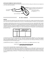
CONNECT GAS SERVICE from meter to control assembly. See previous drawing for typical hook-up. A GROUND-JOINT
UNION MUST BE INSTALLED, EXTERIOR TO THE FURNACE CABINET, SO THE CONTROL ASSEMBLY MAY BE EASILY
REMOVED. A 1/8" NPT plug on the supply pipe at the valve for the purpose of making measurements of the inlet gas pressure
must also  be installed. A manual shut-off valve must be installed in the gas line outside of the furnace casing. The valve
should be readily accessible for turning on or off. A capped drip leg must be installed in the gas supply line as close to the
furnace as possible. A PIPE COMPOUND RESISTANT TO THE ACTION OF LIQUEFIED PETROLEUM GASES MUST BE
USED AT ALL THREADED PIPE CONNECTIONS.

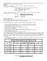
Gas piping should be installed in accordance with local codes and regulations of the utility company.  Consult local gas
company for location of manual main valve.  The gas line should be of adequate size to prevent undue pressure drop and
never smaller than the pipe size to the combination gas valve.  It is recommended that the size of pipe selected be in
accordance with “GAS PIPE CAPACITY TABLE” for the length of pipe required and connected to the furnace as illustrated.

1/2" UNION MUST BE INSTALLED

   OUTSIDE OF UNIT

1/8" NPT TAP

(GAS TEST)

TO GAS
SUPPLY

NOTE: ALL THREADS MUST BE COATED WITH A
PIPE COMPOUND RESISTANT TO THE ACTION OF
LIQUEFIED PETROLEUM GAS.

MANUAL VALVE

4" ABOVE FLOOR

1/8" NPT TAP (GAS TEST)
CAPPED DRIP LEG.

CHECK LOCAL CODES FOR

LENGTH REQUIRED

Содержание GMN SERIES

Страница 1: ...INSTALLATION OPERATING INSTRUCTIONS for GMN SERIES GAS FURNACES PATENT PENDING GoodmanManufacturingCompany L P IO 554 1501 Seamist Houston Texas 77008 11 93...

Страница 2: ...Piping 8 Circulating Supply Air and Return Air 8 9 ElectricalConnection 9 Thermostat Location and Low Voltage Connections 9 10 ToRateFurnace 10 Main Burner Adjustment 11 Safety Controls Functions Che...

Страница 3: ...OW INSTALLATION GAS PIPING See pages 13 14 ELECTRICAL CONNECTIONS See page 16 RETURN AIR See pages 14 15 VENTING See pages 10 12 and VentingTables SUPPLY AIR See pages 14 15 VENTILATION COMBUSTION AIR...

Страница 4: ...ATION RETURN AIR See pages 14 15 VENTING See pages 10 12 andVentingTables ELECTRICAL CONNECTIONS See page 16 SPECIAL BASE See page 6 SUPPLY AIR See pages 14 15 GAS SUPPLY See pages 13 14 COMBUSTION VE...

Страница 5: ...are available from National Fire Protection Association Inc Batterymarch Park Quincy MA 02269 LOCATION Donotinstallthisfurnaceinamobilehome Thefurnacedesignedonlyforinstallationinbuildingsconstructed...

Страница 6: ...WHEN THE FURNACE IS INSTALLED WITH SIDE AIR RETURN DUCTS FAILURE TO LEAVE THIS BASE PLATE INSTALLED COULD CAUSE PRODUCTS OF COMBUSTION TO BE CIRCULATED INTO LIVING SPACE AND CREATE POTENTIALLY HAZARDO...

Страница 7: ...nnectthePowerwirestoVentBlower StackOvertemp wires and Pressure Switch tube leading to Vent Blower Step 4 Remove the three screws item 3 which secure the Vent Blower item 4 to the Heat Shield item 5 o...

Страница 8: ...combustionandventila tionair Thefollowing Figure1throughFigure3 outlinethe minimum combustion ventilation air this furnace and any additional gas fired equipment require when installed in a confined a...

Страница 9: ...refer to Figure 3 3 The combustion and ventilation air openings must be of equal size and sized appropriately Use the table below as a guide TOTAL 1000 BTUH SQ INCH 2000 BTUH SQ INCH 4000 BTUH SQ INC...

Страница 10: ...sed to change from a vertical run to a horizontal run should be type DWV long radius to provide the correct slope in horizontal run If other types are used then 2 45 degree elbows should be used in pl...

Страница 11: ...t for proper fit Wipe socket and pipe with cleaner primer Apply a generous coat of primer to connecting areas DO NOT ALLOW PRIMER TO DRY BEFORE APPLYING CEMENT Apply a thin coat of cement in the socke...

Страница 12: ...r expected snow level c If adjacent to a public walkway the vent termination must be a minimum of 7 feet above the walkway d Avoid area where condensate drainage may be a problem such as flower beds p...

Страница 13: ...ng use a soap and water solution or other approved method DO NOT USE AN OPEN FLAME CONNECTGASSERVICEfrommetertocontrolassembly Seepreviousdrawingfortypicalhook up AGROUND JOINT UNIONMUSTBEINSTALLED EX...

Страница 14: ...INES WHICH HAVE PREVIOUSLY SERVICED ANOTHER APPLIANCE CIRCULATING SUPPLY AIR AND RETURN AIR The circulating air return may be taken from 1 outside the building 2 return ducts from several rooms 3 cent...

Страница 15: ...INGS IN THE CLOSET DOOR AND THE CIRCULATING AIR OPENINGS MUST BE SEPARATED AN ADEQUATE DISTANCE TO PREVENT THE CIRCULATING AIR FROM INTERFERING WITH THE NATURAL FLOW OF VENTILATION AIR FAILURE TO PREV...

Страница 16: ...quipment in polarity sensitive The neutral ground connection must be connected to the equipment white power connector Failure to observe this practice will result in no flame sensing ability THERMOSTA...

Страница 17: ...m the table below resulting in the furnace input being reduced at a rate of 4 for each 1000 feet above sea level U S only ALTITUDE BURNER ORIFICE NATURAL GAS 0 2000 45 3000 47 4000 47 5000 47 6000 48...

Страница 18: ...h the exception of pilot burners 5 Place the furnace into operation 6 Adjust inlet pressure to obtain a pressure range between 5 and 7 W C 7 After 15 minutes of furnace operation time meter with an ac...

Страница 19: ...tem occurs DO NOT tamper with or bypass this switch For more details of the venting installation see the section titled VENTING To check this switch remove the hose from the vent motor with the burner...

Страница 20: ...zed The main valve is opened after the ignitor has been glowing for about 17 seconds If main burner flame is detected by the flame sensor see flame sensor section the burners will continue operation U...

Страница 21: ...ace design rise range the blower speed must be decreased a lower motor speed Prior to making any motor speed changes allow the furnace adequate time to cool down and turn off electric supply to the ap...

Страница 22: ...r assembly 11 Remove the vent blower heat shield and flue collector box 12 Withastiffwirebrushonaflexiblehandleremoveanyloosescalefromtheheatexchanger bothflueopeningandburner opening Use a 1 2 diamet...

Страница 23: ...if service is to be performed 3 Remove control access panel OPERATING INSTRUCTIONS 4 Turn gas control knob clockwise to OFF Do not force 5 Replace control access panel FOR YOUR SAFETY READ BEFORE OPE...

Страница 24: ...rner flame The ignitor will de energize about 7 to 9 seconds If the flame sensor does not detect the presence of main burner flame the gas valve will close and steps 6 through 9 will be repeated for a...

Страница 25: ...ARMS UP GAS VALVE OPENS FLAME SENSED IGNITOR DEACTIVATES VENTER OFF BLOWER OFF BLWR STARTS HTG SPEED BLOWER OFF BLOWER STARTS ON COOLING SPEED CONTACTOR OPENS GAS VALVE OFF VENT MOTOR STARTS TSAT CALL...

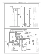
Страница 26: ...WIRINGDIAGRAM 26...

Отзывы: