4
www.goodmanmfg.com
SS-
GM9S80-U
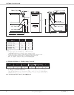
GM9S80-U Dimensions
28”
A
B
1¾”
33⅜”
23
5⁄16
”
1
7⁄16
”
13¼”
20”
27⅞”
Alt. Gas Inlet
Alt. High Voltage
Alt. Low Voltage
Alternate Gas Inlet
High-Voltage Inlet
Low-Voltage Inlet
Alt. Flue Outlet — Horizontal Left
➤
19½”
➤
➤
23”
➤
➤
15”
➤
➤
Minimum Clearances to Combustible Materials
Sides
Rear
Front¹
Vent²
Top
SW
B
1”
0”
3”
6”
1”
1”
¹ 24” clearance for serviceability recommended.
² Single Wall Vent (SW) to be used only as a connector. Refer to the latest editions of the National Fuel Gas
Code NFPA 54/ ANSI Z223.1 (in the USA) and the Canada National Standard of Canada, CAN/CSA B149.1 and
CAN/CSA B142.2 (in Canada).
Note: AMES80 approved for line contact in the horizontal position.
Model
A
B
GM9S800403AU*
14”
12½”
GM9S800603AU*
14”
12½”
GM9S800604BU*
17½”
16”
GM9S800804BU*
17½”
16”
GM9S800805CU*
21”
19½”
Notes
•
voltage wiring can enter through the right or left side of furnace.
Low-voltage wiring can enter through the right or left side of furnace.
•
Installer must supply the following gas line fittings, according to which entrance is used:
Left: One 2” pipe nipple; one 90º elbow; straight pipe; one ground joint union
Right: Five 90º elbow; one ground joint union; various pipe nipples


