


BLOWER PERFORMANCE SPECIFICATIONS
26
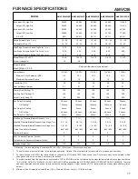
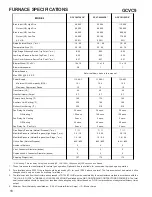
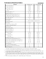
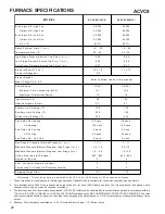
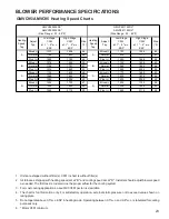
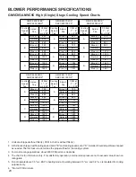
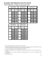
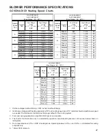
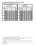
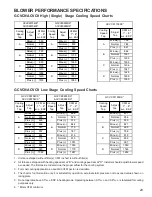
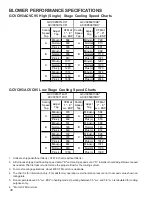
1. Units are shipped without filter(s). CFM in chart is without filter(s).
2. All furnaces shipped with heating speed set at "B" and cooling speed set at "D". Installer should adjust blower speed
as needed. The first task is to determine the proper aiflow for the cooling system.
3. For most cooling applications, about 400 CFM per ton is desirable.
4. The chart is for information only. For satisfactory operation, external static pressure not to exceed value shown on
rating plate.
5. Do not operate above 0.5" w.c. ESP in heating mode. Operating between 0.5" w.c. and 0.8" w.c. is tabulated for cooling
purposes only.
6. * Motor CFM minimum.
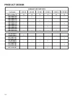
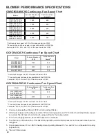
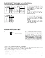
GMVC95/AMVC95 Continuous Fan Speed Chart
GCVC9/ACVC9 Continuous Fan Speed Chart
GCVC95/ACVC95 Continuous Fan Speed Chart
Model
Furnace Maxim um
C FM
C ontinuous Fan
Speed
1,2
GMVC 950453BX*
AMVC950453BX*
1400
420
GMVC950704C X*
AMVC 950704C X*
1760
530
GMVC950905C X*
AMVC 950905C X*
2200
660
GMVC950905D X*
AMVC 950905D X*
2200
660
GMVC951155D X*
AMVC 951155D X*
2200
660
1
C ontinuous fan s peed is 30% of furnace m axim um C FM
2
Three continuous fan s peeds are pos s ible w ith the C TK01AA
therm os tat: 30% , 50% , and 70% of furnace m axim um C FM
Model
Furnace Maximum
CFM
Continuous Fan
Speed
1,2
GCVC90704CX*
ACVC90704CX*
1760
530
GCVC90905DX*
ACVC90905DX*
2200
660
GCVC91155DX*
2350
705
2
Three continuous f an speeds are possible with t he CTK01AA
thermostat: 30%, 50%, and 70% of furnace maximum CFM.
1
Cont inuous fan speed is 30% of furnace maximum CFM
Model
Furnace Maximu m
CFM
Continuous Fan
Speed
1,2
GCVC 9507 14CX*
ACVC950714CX*
1760
530
GCVC 9509 15DX*
ACVC950915DX*
2200
660
1
Cont inuous fan speed is 30% of furnace maximum CFM
2
Three continuou s f an speeds are possible with t he CTK01 AA
thermostat: 30%, 50%, and 70% of furnace maximum CFM.


